Материал: m012900e

Внимание! Если размещение файла нарушает Ваши авторские права, то обязательно сообщите нам

262 • ETHERNET Network architecture

types of applications to be called up world-wide. This makes site independent monitoring, visualization, remote maintenance and control of processes possible.WAGO Kontakttechnik GmbH is a member of IAONA Europe, an organization with the purpose of establishing ETHERNET in automation technology.

5.1 Network architecture – Principles and Regulations

A simple ETHERNET network is designed on the basis of one PC with a network card (NI), one connection cable, one ETHERNET fieldbus node and one 24 V DC power supply for the coupler voltage source.

Each fieldbus node consists of an ETHERNET TCP/IP fieldbus coupler/controller, I/O modules and an end module. The individual bus modules are connected to the ETHERNET TCP/IP fieldbus coupler/controller via an internal bus when they are snapped onto the carrier rail.

It is possible to connect 64 I/O modules to an ETHERNET TCP/IP fieldbus coupler/controller.

Sensors and actuators are connected to the digital or analog I/O modules on the field side. These are used for process signal acquisition or signal output to the process, respectively.

The fieldbus coupler/controller detects all connected I/O modules, creating a local process image of them. This can consist of a mixed arrangement of analog (data exchange of words) and digital (data exchange of bits) bus modules.

Fig. 5-1. Connection principle of a fieldbus node for a network architecture

Fieldbus communication between the master application and the fieldbus coupler/controller takes place via the MODBUS/TCP protocol over ethernet.

MODBUS/TCP maps creates an image of the distributed MODBUS protocol on ETHERNET TCP/IP. The process data can be read and written via ETHERNET . There are numerous applications available which already use this, such as HMI, SCADA, PLC, Soft PLC.

Modular I/O System

ETHERNET TCP/IP

ETHERNET • 263

Network architecture

5.1.1Transmission media

General ETHERNET transmission standards

For transmitting data the ETHERNET standard supports numerous technologies with various parameters of which differ from each other such as i.e. transmission speed, medium, segment length and type of transmission.

10Base5

Uses a 10 mm 50 Ohm coaxial cable for a 10Mbps baseband signal for distances


of up to 500 m in a physical bus topology (often referred to as Thick


ETHERNET).


10Base2

Uses a 5 mm 50 Ohm coaxial cable for a 10Mbps baseband signal for distances


of up to 185 m in a physical bus topology (often referred to as Thin ETHERNET


or ThinNet).


10Base-T

Uses a 24 AWG UTP or STP/UTP (twisted pair cable) for a 10Mbps baseband


signal for distances up to 100 m in a physical star topology.


10Base-F Uses a fiber-optic cable for a 10Mbps baseband signal for distances of up to 4 km in a physical star topology.

(There are three subspecifications: 10Base-FL for fiber-optic link, 10Base-FB for fiber-optic backbone and 10Base-FP for fiber-optic passive).

Tab. 5-1: ETHERNET transmission standards

The four media types are shown with their IEEE shorthand identifiers. The IEEE identifiers include three pieces of information. The first item, “10”, stands for the media.

The third part of the identifier provides a rough indication of segment type or length. For thick coaxial cable, the “5” indicates a 500 meter maximum length allowed for individual thick coaxial segments. For thin coaxial cable, the “2” is rounded up from the 185 meter maximum length for individual thin coaxial segments. The “T” and “F” stand for ‘twisted pair’ and ‘fiber optic’, and simply indicate the cable type.

10Base-T

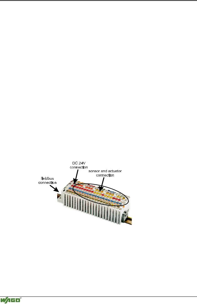
10Base-T Standard is used for the WAGO ETHERNET fieldbus coupler. This allows for simple and economical network architecture using STP/UTP cable as the transmission medium.

STP is shielded twisted pair category 5 cables (CAT 5). UTP is twisted pair without shielding implemented.

Parameter

10BaseT

Medium

Twisted-Pair

Signaling technology

Baseband

Signaling code

Manchester encoding

Bit rate (Mbit / s)

10

Topology

Star

Max. segment length (m)

100

Max. packet size (Byte)

1512

Min. packet size (Byte)

64

Tab. 5-2: Important parameters of the 10Base-T ETHERNET standard

Modular I/O System

ETHERNET TCP/IP

264 • ETHERNET Network architecture

Wiring of the fieldbus nodes with 10Base-T technology

A crossover cable is required for direct connection of a fieldbus node to the network card of the PC.


Fig. 5-2: Direct connection of a node with crossover cable

g012906d

If several fieldbus nodes are to be connected to a network card, the fieldbus nodes can be connected via an ETHERNET switch or hub with straight through/parallel cables.

TD+

TD-

RD+

RD-

TD+

hub

TD+

TD+


TD-


TD-

TD-

RD+


RD+

RD+

RD-


RD-

RD-


Fig. 5-3: Connection of a node by means of a hub with parallel cables

g012908e

A switch/hub is a device that allows all connected devices to transmit and receive data with each other. This can also be viewed as a “data traffic cop” where the hub “polices” the data coming in and going out so that it will be transmitted to the correct node. WAGO recommends using a switch rather then a hub, this will allow for a more deterministic architecture.

Attention

The cable length between the node and the hub can not be longer than 100 m (328 ft.) without adding signal conditioning systems (i.e. repeaters). Various possibilities are described in the ETHERNET standard for networks covering larger distances.

Modular I/O System

ETHERNET TCP/IP

ETHERNET • 265

Network architecture

5.1.2Network topologies

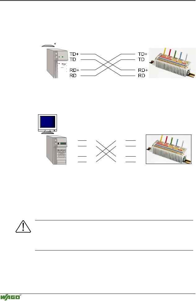
In the case of 10Base-T several stations (nodes) are connected using a star topology according to the 10Base-T ETHERNET Standard.

Therefore, this manual only deals with the star topology, and the tree topology for larger networks in more detail.

Star topology

A star topology consists of a network in which all nodes are connected to a central point via individual cables.


Fig. 5-4: Star topology


G012906e

A star topology offers the advantage of allowing the extension of an existing network. Stations can be added or removed without network interruption. Moreover, in the event of a defective cable, only the network segment and the node connected to this segment is impaired. This considerably increases the fail-safe of the entire network.
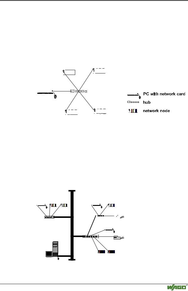
Tree topology

The tree topology combines characteristics of linear bus and star topologies. It consists of groups of star-configured workstations connected to a linear bus backbone cable. Tree topologies allow for the expansion of an existing network, and enables schools, etc. to configure a network to meet their needs.


Nodes


Nodes


Concentrator

(Hub)

Backbone

Cable

Fig. 5-5: Tree topology

G012904e

Modular I/O System

ETHERNET TCP/IP

266 • ETHERNET Network architecture

5-4-3 Rule

A consideration in setting up a tree topology using ETHERNET protocol is the 5-4-3 rule. One aspect of the ETHERNET protocol requires that a signal sent out on the network cable must reach every part of the network within a specified length of time. Each concentrator or repeater that a signal goes through adds a small amount of time. This leads to the rule that between any two nodes on the network there can only be a maximum of 5 segments connected through 4 repeators/concentrators. In addition, only 3 of the segments may be populated (trunk) segments if they are made of coaxial cable. A populated segment is one which has one or more nodes attached to it. In Figure 5-5, the 5-4-3 rule is adhered to. The furthest two nodes on the network have 4 segments and 3 repeators/concentrators between them.

This rule does not apply to other network protocols or ETHERNET networks where all fiber optic cabling or a combination of a backbone with UTP cabling is used. If there is a combination of fiber optic backbone and UTP cabling, the rule is simply translated to 7-6-5 rule.

Cabling guidelines

"Structured Cabling" specifies general guidelines for network architecture of a LAN, establishing maximum cable lengths for the grounds area, building and floor cabling.

Standardized in the standards EN 50173, ISO 11801 and TIA 568-A, "Structured Cabling" forms the basis for a future-orientated, application-independent and cost-effective network infrastructure.

The cabling standards define a domain covering a geographical area of 3 km and for an office area of up to 1 million square meters with 50 to 50,000 terminals. In addition, they describe recommendations for setting up of a cabling system.

Specifications may vary depending on the selected topology, the transmission media and coupler modules used in industrial environments, as well as the use of components from different manufacturers in a network. Therefore, the specifications given here are only intended as recommendations.

Modular I/O System

ETHERNET TCP/IP