Материал: m012900e

 S
S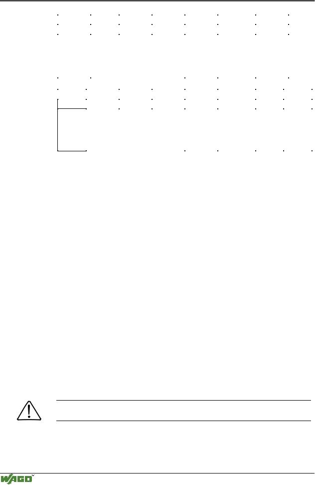
I/O modules • 255
RS485C interface 750-653
An example:
The module is initialized.
- The initialization bit in the control byte is set.
Output byte 0 |
|
Control byte |
Output byte 2 |
Output byte 1 |
0x00 |
|
0000.0100 |
0x00 |
0x00 |
- After the initialization has been executed, the status byte will give back 000.0100.
Input |
Status byte |
Input |
Input |
|
|
|
|
|
|
byte 0 |
|
byte 2 |
byte 1 |
|
XX |
0XXX.X0XX |
XX |
XX |
Module is still being reset. |
XX |
0XXX.X1XX |
XX |
XX |
Initialization completed. |
Sending of the data string "Hello” in ASCII code:
-The first 3 characters and the buffer length of 3 are transmitted.
Out- |
|
Control byte |
Output |
Output |
|
put |
|
|
byte 2 |
byte 1 |
|
|
|
|
|||
byte 0 |
|
|
|
|
|
|
|
|
|
|
|
‘H’ (0 x |
|
0011.0000 |
‘l’ (0 x 6C) |
‘e’ (0 x |
Entering data to module |
-The transmission request bit (TR) is inverted.
Out- |
|
Control byte |
Output |
Output |
|
put |
|
|
byte 2 |
byte 1 |
|
|
|
|
|||
byte 0 |
|
|
|
|
|
|
|
|
|
|
|
‘H’ |
|
0011.0001 |
‘l’ |
‘e’ |
Send Data |
-As soon as TR=TA, the rest of the data can be sent.
Input |
Status byte |
Input |
Input |
|
|
|
|
|
|
byte 0 |
|
byte 2 |
byte 1 |
|
XX |
0XXX.XXX0 |
XX |
XX |
The data is still being transferred |
XX |
0XXX.XXX1 |
XX |
XX |
Data transfer completed. |
-The last 2 characters and the buffer length of 2 are transmitted.
Output byte 0 |
|
Control byte |
Output byte 2 |
Output byte 1 |
‘l’ |
|
0010.0001 |
XX |
‘o’ (0 x 6F) |
-The transmission request bit (TR) is inverted.
Output byte 0 |
|
Control byte |
Output byte 2 |
Output byte 1 |
‘l’ |
|
0010.0000 |
XX |
‘o’ |
Modular I/O System
ETHERNET TCP/IP