Материал: anglish
4. This boring mill enabled James Watt to solve the problem of making his cylinder steam-tight.
5. Today machine tools and metal cutting are not very important for industry.
Завдання 19. Виправте хибні твердження, подані в завданні 18.
Завдання 20. Дайте заголовок до тексту 6Б.
Завдання 21. Складіть план переказу тексту 6Б та перекажіть текст.
Завдання 22. Перекладіть подані нижче фрагменти речень, звертаючи увага на форму присудка – пасивний стан . Потім змініть форму присудка на активний стан , зробивши усі інші необхідні зміни в реченнях:
his first cylinder was manufactured from sheet metal,…… ;
It could not be made steam-tight........: the problem was solved by John Wilkinson,…….; the boring bar was supported on bearings........; the boring bar could be rotated and fed through the cylinder........; much research effort has been expended........ .
Завдання 23. Підготуйте письмове повідомлення на тему:” Деякі факти з історії розвитку обробки металів різанням та її місце у сучасній промисловості” (Обсяг 1000 тис. знаків).
Notes and commentary
modern lathes — современные токарные станки
accurate and complex devices — точные и сложные приборы
precision lathe — прецизионный токарный станок (для точной обработки)
main casting of the lathe is called a bed — основной каркас токарного станка называется станиной
accurately machined ways — аккуратно обработанные направляющие станка
on which slide the saddle and the tailstock — по которым перемещаются салазки и задняя бабка
of inverted V-type — иметь форму перевернутой букві v
are integral with the casting — сделаны заодно со станиной
on the machine — зд. на станке
is located true with the ways — размешается параллельно направляючим
at the left-hand end — с левого конца
all geared head type — токарный станок с передней бабкой с од-ношкифным приводом и коробкой скоростей
the lathe spindle — шпиндель токарного станка
plain bearings — подшипники без вкладышей
thrust washers — упорные шайбы
to prevent end play — предотвратить продольный люфт
external thread — наружная резьба
face plate — планшайба
chuck back plate — диск универсальной планшайбы
taper hore — конусная расточка to drive a train of wheels — приводить в движение систему колес
lead screw — ходовой винт
feed shaft — валик подачи
firmly clamped to it — прочно прикрепленный к нему
at any position along its length — в любом месте по всей его длине
sliding sleeve — скользящая втулка
to carry the tool post slide — перемещать резцедержательные салазки
lateral movement — поперечное движение
towards and away from the head-stock — no направлению к передней бабке и обратно
at right angles to the bed - под прямыми углами к станине
step-cone head — передняя байка со ступенчатым приводом
geared-head — передняя бабка с постоянной скоростью рема я и коробкой скоростей
built-in motordrive head — передняя бабка со встроенным в нее мотором
single-pulley — одношкифный
V-belts — клиновые ремни
infinite number of steps — бесконечное число ступеней
by merely turning a dial — простым поворотом шкалы (лайба)
THE MAIN TYPES OF MODERN LATHES
The Automatic Lathe is so designed that all' of the tool movementes are automatically controlled, although the work must be inserted and removed by an attendant.
Turret Lathe.— The characteristic feature of a turret lathe is the turret which is mounted upon a carriage and contains the tools which are successively brought into the working position by indexing or rotating the turret. Many turret lathes also have systems of stops or gauges for controlling the travel of the turret carriage and cross-slide, in order to regulate the depth of a bored hole, the length of a cylindrical part or its diameter.
Automatic Screw Machine.— The original field of the automatic screw machine was the making of screws. This field was quickly enlarged to include the making of all kinds of small nuts, washers, pins, collars, etc., and, at the present time, machines of this class are capable of a great variety of operations-Characteristic features of screw machines in general are means for automatically locating successive tools in the correct working position, the automatic changing of feeds and speeds and the presenting of new stock to the tools for a similar series of operations. These various movements, which are entirely automatic, are obtained principally from cams which are rotated at predetermined speeds. There are two general classes of screw machines: a single work-spindle and several work-spindles — usually four, five or six spindles.
NOTES AND COMMENTARY
lathe — револьверный станок
mounted upon a carriage — установленный (смонтированный) на каретке
indexing or rotating — периодический поворот или вращение детали или части станка на определенный угол
slops or gauges — стопоров или фиксаторов
screw machine — станок для нарезания винтов
means for automatically locating successive tools — средства для автоматического размещения (последовательных) промежуточных инструментов
correct working position — npaвильное рабочее положение
DRILLING MACHINES
Drilling machines which are used mainly for drilling holes in machine parts, are made in many different types designed for handling the various classes of work.
The upright drilling machine is the type most commonly used, and the name applied to this class indicates that the genera! design of the machine is vertical, and also that the drill spindle is in a vertical position.
The radial drilling machine. The main advantage of a radial machine is that the drill can be moved over the work to any desired position, so that a large number of holes can be drilled in the work without moving it.
The sensitive drill is a small machine of light construction, which possesses sensitive qualities which are of value in drilling holes in delicate work.
The multiple-spindle type is built in both vertical and horizontal design.
It can perform a number of operations on a component without the necessity of changing tools.
Gang Drills. When a number of single-spindle drilling machine columns are placed side by side on a common base and' have a common work table, the machine is known as a gang drill. Each spindle is independently controlled as to speed and feed so that a number of operations may be performed in succession and simultaneously upon the machine, fn this machine work is moved progressively from one spindle to the next,
NOTES AND COMMENTARY
drilling machines — сверлильные станки
machine-parts — детали машин
toe handling the various classes of work — для выполнения различных видов работ
upright drilling machine — вертикальный сверлильный станок
radial drilling machine — радиалъно-сверлильный станок
ever the work — над деталью
sensitive drill — быстроходный сверлильный станс к с ручной подачей
delicate work — мелкая деталь
side by side on a common base — рядом, на общем основании
as to speed and feed so that — что касается скорости и подачи так, то
upon a machine — на станке
MILLING MACHINES
Milling is the process of removing metal with rotating cutters.
The essential features of most milling machines are a power-driven table on which the work is done, and a spindle carrying one or more multiple-toothed cutters, slots or grooves.
The horizontal milling machine consists of a main casting in which is mounted the spindle and its gear drive, and the feed gear-box. On the front of this casting is a vertical V-guide on which is mounted the knee. The knee is raised or lowered by a telescopic jack screw. A saddle slides from front to back on V-guides on the top of the knee. The work table is mounted in V-guides on the saddle. The table is provided with movement in two directions at right angles to each other in the horizontal plane, and with vertical movement relative to the cutter, whose height is permanently fixed.
The cutter is mounted on an arbor, and held in the desired position by spacing washers and a locking nut.
The type of a cutter mainly used on the horizontal miller is what is known as a side and face cutter, that is, a cutter provided with cutting edges on both sides and on periphery. For large flat surfaces, roller milling cutters are used, having cutting edges in the form of helix about the axis of rotation.
NOTES AND COMMENTARY
milling machines — фрезерные станки
rotating cutters ,— вращающиеся фрезы
power-driven table — столик с механическим приводом
multiple-toothed cutters — много-зубчатые фрезы
gear drive — шестеренчатый привод
feed gear-box -— зубчатая коробка передач
V-guide — V-образная направляющая
jack screw — дом кратный винт
on the top of the knee — на верху кронштейна
at right angles — под прямыми углами
relative to — относительно
is permanently fixed — постоянно закреплен
is mounted on an arbor — смонтированный на шпинделе
spacing washers and a locking nut —
распорные шайбы и зажимные гайки
side and face cutter — боковая и лобовая фреза
cutting edges on both sides and on periphery —
режущие кромки по бокам и на периферии
in the form of helix about the axis of rotation —
в форме спирали по оси вращения
THE SHAPER
A shaper is a machine that forms surfaces by successive reciprocating cuts of a tool over the work. The work is stationary with reference to the tool but moves laterally in small steps so that the successive cuts can be made. Although most of the work performed on shapers consists of plane horizontal surfaces, it is also possible to finish vertical and angular surfaces, and, with the proper tools and accessories, even curved surfaces may be machined.
The size of a shaper is determined by the longest stroke of the ram.
Shapers are driven by belt from a countershaft, by direct connected motor, or by hydraulic power.
NOTES AND COMMENTARY
bу successive reciprocating cuts of a tool over the work — последовательным возвратно-поступательным снятием металла режущим инструментом, перемещающимся над деталью
with the reference to — относительно
in small steps — малыми подачами
plane horizontal sui fares — плоские горизонтальные
поверхности
THE PLANER
P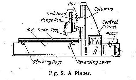 laners
are essentially for machining plane surfaces which are larger than
can be cut or reached on the shaper. The modern planer with
modern electric controls has a high output.
laners
are essentially for machining plane surfaces which are larger than
can be cut or reached on the shaper. The modern planer with
modern electric controls has a high output.
The planer has a reciprocating table which travels beneath a cross bar on which the tool heads are mounted. Normally бпе or two tool heads are mounted on the cross bar, but additional tools, generally for cutting vertical faces, may be mounted on the columns supporting the cross bar. The usual design (Fig. 9) comprises two vertical columns between which the table reciprocates, The cross bar is so mounted that it can slide vertically on these columns. All motions for feed or cut take place either by dropping the cross bar, moving- the tool head across: the cross bar, or lowering the tool holder mounted on the tool head. The first two of these motions are generally power or hand-operated but the last is often hand-operated only.
The table is normally operated by some form of rack-and-pinion or spiral drive.
Modern high- speed planers are now fully electrified.
NOTES AND COMMENTARY
planer — продольно-строгальный станок
plane surface — плоская поверхность
high output — высокая производительность
a reciprocating table — движущийся взад и вперед стол
cross bar — поперечина
tool heads — инструментальные головки
motions for feed or cut take place-движения для подачи или обработки режущим инструментом происхидят
hand-operated — управляемый вручную
rack-and-plnion drive —- зубчато-реечный привод
spiral drive — привод винтовыми колесами
SLOTTER
T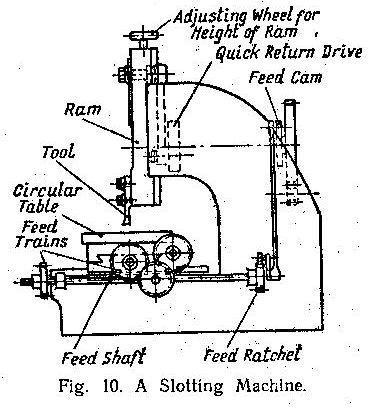 he
slotting machine
may be looked upon as a vertical shaping machine. It machines the
internal surfaces of a casting or forging and can do circular work by
virtue of its pivoted
he
slotting machine
may be looked upon as a vertical shaping machine. It machines the
internal surfaces of a casting or forging and can do circular work by
virtue of its pivoted
table. Originally slotters were used for cutting keyways, machining the square holes in such parts as dog clutches and they are still used for this work in small shops.
The work table is usually circular and provided with T-slots for clamping the work. It is mounted on two horizontal slides at right angles to each other and can be moved with either hand or intermittent automatic feed in either direction along therri. It can also be rotated in the horizontal plane about its axis in either direction by hand or automatically.
Slotters are usually provided with three or four speeds, obtained either by cone pulley or gear-box.
NOTES AND COMMENTARY
may be looked upon — может рассматриваться
by virtue of its pivoted table — благодаря тому, что стол поворачивается на оси
cutting keyways — прорезывание шпоночных канавок (пазов)
dog clutches — кулачковая муфта
T-slots for clamping the work — Т-образные пазы для зажима детали
at right angles to each other — пол прямым углом друг к другу
in either direction — в любом направлении
in the horizontal plane about its axis — в горизонта дан ой плоскости вокруг своей оси
cone pulley — ступенчатый шкив
|
[material: steel, brass, aluminium (Am. aluminum), plastics, etc.; in the following, steel was chosen as an example]
3 -7 steel girders
9 square iron (Am. square stock) 10 flat bar 11 strip steel
|
75 - 76 needle roller bearing
97 - 107 absorption dynamometer
|