Материал: Russian Journal of Building Construction and Architecture
Issue № 3 (43), 2019 |
ISSN 2542-0526 |
In conclusion, what sets the model NN apart is its credibility and reliability.
Conclusions. The paper presents the analytical model designed using artificial neural networks NN for predicting the coupling strength limit of ferroconcrete. In order to design the analytical model, experimental studies of pulling of the anchor out of concrete were conducted. Based on the result analysis presented in the paper, the following can be concluded.
1.The methods of soft calculations were shown to be applied as a tool for processing and inputting empirical data of final coupling strength with different strength characteristics of concrete. All of the predicted values were correct and comparable with the experimental data. Therefore the suggested NN can be considered as a viable model with a good predicting capacity.
2.The experimental values along the entire dataset and an average error between the predicted and actual values were shown to be almost identical for the model.
If the resulting model is analyzed using the correlation index, it can be deemed adequate along the entire value range. The correlation coefficient for the database was 0.947. Besides, for the testing of the database the correlation coefficients 0.937 for the first, 0.969 and 0.969 for the last ones were obtained. Despite the fact that the database for testing was not used for the training, a high prediction level was achieved associated with a low average absolute error percentage and high correlation coefficients. This indicates that the developed model is credible and reliable.
3.The statistical analysis relying on the values of MSE also showed that the suggested formulations of NN had relatively low error indices. According to the general trends in the efficiency evaluation, we can say that the prediction model NN can be considered the most optimal one out of those currently employed.
4.As NN is designed using the computer software, manual calculation is daunting unless computational technology is employed. However, the model NN comes in handy when more accurate measurements need to be predicted. Use of electronic computing eliminates challenges associated with calculations. The solution to the problem could be computerization of the model NN by means of a simple electronic spreadsheet. Therefore this insignificant fault can easily be eliminated.
References
1.Madatyan S. A., Tuleev T. D., Fridlyanov V. N. e. a. Ankerovka nenapryagaemoi sterzhnevoi armatury [Nonstressed anchor rod of rebar]. Beton i zhelezobeton, 1990, no. 12, pp. 9––11.
2.Kotova K. S., Slavcheva G. S. Izuchenie stsepleniya razlichnykh vidov armatury s penobetonom [The study of the adhesionof the various typesof rebar with foam].Stroitel'stvo i rekonstruktsiya,2018,no.1(75),pp.114––123.
3.Nazarenko P. P. Kontaktnoe vzaimodeistvie armatury v betone v elementakh zhelezobetonnykh konstruktsii. Avtoref. diss. kand. tekhn. nauk [Contact interaction of reinforcement in concrete in elements of reinforced concrete structures. Dr. eng. sci. diss.]. Moscow, 1998. 34 p.
15

Russian Journal of Building Construction and Architecture
4.Oatul A. A. Predlozheniya k postroeniyu teorii stsepleniya armatury s betonom [Proposals for the construction of the theory of adhesion of reinforcement with concrete]. Beton i zhelezobeton, 1968, no. 12, pp. 8––10.
5.Sudakov G. N. Metod rascheta armatury periodicheskogo profilya s betonom s uchetom vnutrennikh kontaktnykh treshchin. Diss. kand. tekhn. nauk [Method of calculation of periodic profile reinforcement with concrete taking into account internal contact cracks. diss. kand. tekhn. nauk. Cand. eng. sci. diss.]. Moscow, NIIZhB Publ., 1982. 205 p.
6.Kholmyanskii M. M., Gol'dfain B. S., Kol'ner V. M. e. a. Stseplenie sterzhnevoi armatury periodicheskogo profilya s betonom [The clutch rod of rebar periodic profile with concrete]. Stseplenie armatury s betonom. Moscow, 1971, pp. 31––37.
7.Kholmyanskii M. M. Kontakt armatury s betonom [Rebar contact with concrete]. Moscow, Stroiizdat Publ., 1981. 184 p.
8.Nikolyukin A. N., Yartsev V. P., Kolomnikova I. I. e. a. Eksperimental'nye issledovaniya prochnosti stsepleniya stekloplastikovoi armatury s tsementno-peschanym betonom [Experimental studies of the adhesion strength of fiberglass reinforcement with cement-sand concrete]. Transportnye sooruzheniya, 2019, vol. 6, no. 1. doi: 10.15862/02SATS119.
9.Adhikary B. B., Mutsuyoshi H. Prediction of shear strength of steel fiber RC beams using neural networks. Constr. Build. Mater, 2006, no. 20 (9), pp. 801––811.
10.Dahou Z. H., Sbartai Z. M., Castel A. e. a. Artificial neural network model for steel-concrete bond prediction. Eng. Struct, 2009, no. 31 (8), pp. 1724––1733.
11.Ashour A. F., Alvarez L. F., Toropov V. V. Empirical modeling of shear strength RC deep beams by genetic programming. Comput. Struct, 2003, no. 81 (5), pp. 331––338.
12.Duan Z. H., Kou S. C., Poon C. S. Prediction of compressive strength of recycled aggregate concrete using artificial neural networks. Constr. Build. Mater, 2013, no. 40, pp. 1200––1206.
13.Mermerdas K., Guneyisi E., Gesoglu M. e. a. Experimental evaluation and modeling of drying shrinkage behavior of metakaolin and calcined kaolin blended concretes. Constr. Build. Mater, 2013, no. 43, pp. 337––347.
14.Goh A. Prediction of ultimate shear strength of deep beams using neural networks. ACI Struct. J., 1995, no. 92 (1), pp. 28––32.
15.Fairbairn E., Silvoso M. M., Filho R. e. a. Optimization of mass concrete construction using genetic algorithms. Comput. Struct, 2004, no. 82 (2––3), pp. 281––299.
16.Rehm G. Ueber die Grundlagen des Verbundes zwischen Stahl und Beton. Deutscher Ausschuss for Stahlbeton, 1961, no. 138. 59 p.
17.Sadowski L. Non-destructive evaluation of the pulloff adhesion of concrete floor layers using rbf neural network. J. Civ. Eng. Manag, 2010, no. 19 (4), pp. 550––560.
18.Sadowski L. Non-destructive investigation of corrosion current density in steel reinforced concrete by artificial neural networks. Arch. Civ. Mech. Eng., 2013, no. 13 (1), pp. 104––111.
19.Sakla S. S., Ashour A. F. Prediction of tensile capacity of single adhesive anchors using neural networks. Comput. Struct., 2005, no. 83, pp. 1792––1803.
20.Yartsev V. P., Nikolyukin A. N., Pluzhnikova T. M. Аssessment and modeling of bond strength of corroded reinforcement in concrete structures. Advanced Materials and Technologies, 2018, no. 3, pp. 70––82.
16

Issue № 3 (43), 2019 |
ISSN 2542-0526 |
HEAT AND GAS SUPPLY, VENTILATION, AIR CONDITIONING,
GAS SUPPLY AND ILLUMINATION
DOI 10.25987/VSTU.2019.3.43.002
UDC 532.51
A. P. Levtzev1, A. N. Makeev2
CONTROLLABLE SHOCK UNIT OF THE OPPOSITE CONSTRUCTION
FOR HEAT SUPPLY SYSTEMS WITH PULSE CIRCULATION
OF THE HEAT CARRIER
National Research of the Ogarev Mordovia State University,
Institute of Mechanics and Energy1, 2
Russia, Saransk
1D. Sc. In Engineering, Head of the Dept. of Thermal Electric Systems, tel.: (8342)25-41-01, e-mail: levtzev@mail.ru
2PhD in Engineering, Assoc. Prof. of the Dept. of Thermal Electric Systems, Head of the Learning Scientific Laboratory “Pulse Systems of Heat and Water Supply”, tel.: (8342)25-41-01, e-mail: tggi@rambler.ru
Statement of the problem. The relevance of the topic is due to the need to seek out technical solutions to create controlled pulsations of the coolant used for improving the energyefficiencyof heating systems. The known designsofself-sustainingimpact unitsdonotmeetthereliabilityrequirementsofsuch systems.
Results. A technical solution has been obtained for the opposite structure with an external control for switching itsvalves. Theschemeoftheexperimental setup for itstesting isdescribed. Theresultsofstudies of its characteristics are presented: the range of stable operation is established; the dependence of the pressureincrement at themoment ofa water hammer on thechangein theflowrateoftheworkingmedium at a fixed pulse generation frequency was obtained; the dependence of pressure change at the moment of water hammer on thevalveswitching frequencywhilemaintaininga specified disposablepressurewasobtained;a mathematicalmodel oftheimpactnodehasbeen developed andsimulation resultsarepresented.
Conclusions. The resulting design of the shock unit allows one to control the degree of a pressure increase in a pulse in a relatively wide range of variations in the flow rate of the working medium and can be used in the heat supply system to localize heat transfer, transform the disposable head from one hydraulic circuit to another and clean heat transfer surfaces from scale.
Keywords: hydraulic shock unit, chock valve, hydraulic chock, momentum of the movement of the working medium, pulsed circulation of the coolant, pulse heating system.
Introduction. Organization of impulse and pulsing circulation of a heat carrier for improving
heat exchange has become widespread domestically[16, 18, 23] and abroad [13, 14, 17, 22].
* The present article is prepared as part of the Russian Federation President grant for the government's support of young Russian scientists holding a PhD degree МК-1408.2018.8. The subsidy agreement is № 075-15-2019-584. © Levtzev A. P., Makeev A. N., 2019
17

Russian Journal of Building Construction and Architecture
E. g., in [1, p. 134] there are experimental data indicating a possible 3.5 times increase in the heat-exchange coefficient during pulsation of a heat carrier in a cylindrical duct. In [12] due to the organization of oscillatory movement of a heat carrier generated by rigid flaps there is a 134 % increase in heat transfer. Positive experiences in intensifying heat transfer during oscillatory movement of a heat carrier are reported in [11, 15, 21].
Based on the previous research, heat and water supply systems have started experiencing optimization as well where impulse and pulsing circulation of a heat carrier has also been used for improving other components of their energy performance [2]. E. g., along with intensification of heat processes it has become possible to ensure self-purification of heat-transmitting surfaces of limescale and sludge by a moving heat carrier itself while transformation of available head pressure from one of hydraulic contours into another with no use of extra pumps is now a possibility [7].
At the initial stage of the development of impulse systems of heat and water supply [3] use of scheme solutions for one-liquid [9, 19] and two-liquid [20] hydraulic rams for organizing oscillatory circulation of a heat carrier was justified by means of their relative simplicity and reliability as well as the fact that their nodes for creating a local hydraulic shock could operate for decades in the automatic mode with no maintenance needed [10, с. 4].
However, experience of operating self-powered hydraulic nodes using these water-pumping setups has shown that their use is not justified at all. Here are the reasons why.
Firstly, self-powered hydraulic nodes operate only in a relatively narrow range of change of the consumption of the operating environment [4]. There is no automatic closure of the flap which is lower than the minimum acceptable one as specified by construction parameters of a setup and if the maximum acceptable value is exceeded, the valve of the hydraulic node does not open.
Secondly, the frequency of self-powered hydraulic nodes depends on the consumption of the operating environment through them. The larger is the consumption, the larger is the closure frequency and the other way round. This does not allow a specified frequency of pulsations of a heat carrier to be provided as its consumption changes, e. g., through a hot water supply heat carrier as heat load is regulated.
Thirdly, self-powered hydraulic nodes are very sensitive to changes of any parameters of a hydraulic system operated alongside them. If hydroshock water-pumping setups are used, the length of an alimentary pipe, available head pressure of the operating environment, height of injected water, quality and amount of used energy of generated hydraulic shocks are stable [6], which is not the case for a heat supply system with a developed user network. As parameters of
18
Issue № 3 (43), 2019 |
ISSN 2542-0526 |
a heat carrier, water pumping as well as transformation of the impulse of the movement amount are constantly changing, there are occasional interruptions in the operation of such a node. The above does not allow the application range of impulse and pulsing oscillatory circulation of a heat carrier to be further explored in order to intensity heat transfer as well as to transform available pumping from one hydraulic contour into another and provide self-purification of heat-transmitting surfaces over numerical values and qualitative indices obtained by means of self-powered hydraulic nodes. Therefore it is essential to search for new structures for creating manageable hydraulic shocks that have no above disadvantages to enable energy performance in heat supply systems to be improved as transition towards impulse circulation of a heat carrier is made.
The objective of the study is to develop the structure and to examine the characteristics of a hydraulic node of an opposite structure with external operation of alternating opening of its valves.
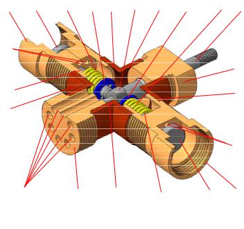
1. Developing a technical solution of a hydraulic shock of an opposite structure with possible external operation. A sketch of the suggested hydraulic node is shown in Fig. 1.
Fig. 1. Hydraulic node with external operation: 1 is a hollow body; 2 is the first inlet; 3 is the second inlet; 4 is the first hydraulic valve; 5 is the first rod; 6 is the first bushing; 7 is a shaft; 8 is cam; 9 is the first spring; 10 is the first retaining ring; 11 is a centering flange; 12 is a directing bushing; 13, 14 are extra coaxial inlets; 15 are end-to-end ducts; 16 are end-to-end cuts; 17 is the second shock valve; 18 is the second rod;
19 is the second bushing; 20 are end-to-end ducts; 21 is the second spring; 22 is the second fixing ring
The setup operates in the following way [8]. First, a free face of the first bushing 6 rigidly joined with the first inlet 2 of the hollow body 1 and a free face of the second bushing 19 rigidly joined with the second inlet 3 of the hollow body 1 are switched to the source of the ope-
19