Материал: Стандарт MIL-STD-202G
MIL-STD-202G
METHOD 307
CONTACT RESISTANCE
1. PURPOSE. The purpose of the contact resistance test is to determine the resistance offered to a flow of current during its passage between the electrical contacting surfaces of connecting components, such as plugs, jacks, connectors, and sockets, or between the electrical contacts of current controlling components, such as switches, relays, and circuit breakers. For practical reasons, lead and terminal resistances may be included in the actual measurement, as well as the contact resistance proper. In many applications it is required that the contact resistance be low and stable, so that the voltage drop across the contacts does not affect the accuracy of the general circuit conditions. If large currents are passed through high resistance contacts, excessive energy losses and dangerous overheating of the contacts may occur.
1.1 Precautions. Contact resistance values between two contacting surfaces are influenced by such factors as the resistivities of the surface materials; contact pressure; area; shape; condition (including relative cleanliness, smoothness, and hardness) of surfaces; current; open circuit voltage appearing at the contacts during interruption of current; temperature; and thermal conductivity of leads. These factors should be considered in designing test jigs or clamps, or in performing contact resistance measurements. Contact resistances are usually measured by a 4- terminal procedure, using a Kelvin bridge, or by the voltmeter-ammeter method. The test current used is usually the maximum rated current for the contacting surfaces involved. In measuring contact resistance, it is important to keep the specimen free from vibration, and to prevent changes in normal contact pressure which might result from improper application of test jigs or clamps.
2.PROCEDURE. The resistance of the contacts may be measured directly using a Kelvin bridge, or indirectly using the voltmeter-ammeter method, ammeter-potentiometer method, or other suitable means. The maximum allowable measurement error shall be 5 percent. The point of measurement shall be the point at which the external leads are normally connected to the terminals. Connections between the specimens and the measuring apparatus shall be made as specified, using suitable connecting jigs or clamps, where required. The magnitude of direct current to be passed through the contacts during the measurement and, when necessary, the maximum open circuit test voltage shall be as specified. A series resistor may be used provided the specified open circuit test voltage is not exceeded. The number of activations to cleanse the contacts prior to measurement, the number of test activations, and the number of measurements per activations to be made on each contact shall be as specified.
3.SUMMARY. The following details are to be specified in the individual specification:
a.Method of connection (see 2).
b.Test current (see 2).
c.Maximum open circuit test voltage, if applicable (see 2).
d.Number of activations prior to measurement (see 2).
e.Number of test activations (see 2).
f.Number of measurements per activation (see 2).
METHOD 307 24 October 1956
1 of 1
MIL-STD-202G
METHOD 308
CURRENT-NOISE TEST FOR FIXED RESISTORS
1. PURPOSE. This resistor noise test method is performed for the purpose of establishing the "noisiness" or "noise quality" of a resistor in order to determine its suitability for use in electronic circuits having critical noise requirements. This method is intended as a standard reference for the determination of current noise present in a resistor, for use in an application with specific current-noise requirements. It is not intended as a general specification requirement. Interference caused by the generation of spurious noise signals in parts tends to mask the desired output signal, thus resulting in loss of information. For low-level audio frequency and other low-frequency circuits, where low-noise parts are used, resistors may become an important source of interfering noise. One source of noise in a resistor is molecular thermal motion which generates a fluctuation voltage termed "thermal noise". It is not necessary to determine the magnitude of thermal noise by measurement since the mean-square value of the fluctuation voltage is predictable from Nyquist's equation, which shows the mean-square value to be proportional to the product of resistance, temperature, and the pass band of the measuring system. Generally, an increase in fluctuation voltage appears when direct current (dc) is passed through resistive circuit elements. The increase in fluctuation voltage is termed "excess noise" or "current noise". The magnitude of current noise is dependent upon many inherent properties of the resistor such as resistive material and other factors such as processing, fabrication, size and shape of resistive element, etc. Since there is no apparent functional relationship between current noise and many of these factors, current noise generally cannot be predicted from physical constants. Therefore, it is necessary to measure current noise to determine its magnitude. The method employed in this test has been designed to evaluate accurately the "noisiness" or "noise quality" of individual resistors in terms of a noise-quality index. The noise-quality index, expressed in decibels (dB), is a measure of the ratio of the root-mean-square (rms) value of current-noise voltage, in microvolts ( v), to the applied dc voltage, in volts. The pass band associated with the noise-quality index is one frequency decade, geometrically centered at 1,000 hertz (Hz). This index is termed the "microvolts-per-volt-in-a-decade" index. In the design of circuits, an added advantage accrues from the definitiveness of the index which allows the estimation of interference attributable to current noise. Conversely, for a given limit of current-noise interference in a particular circuit design, a maximum acceptable value of the index may be established. Ordinarily, it is not necessary to duplicate the operating conditions of the particular circuit design when measuring the current noise. The noise quality of populations of resistors may be reasonably estimated by measurement of the index of representative groups of resistors using suitable sampling procedures. Measurements on sample groups tend to have a normal distribution and once representative parameter values for the distribution have been established (the mean and standard deviation), such parameter values would serve as norms in judging "noisiness" and product uniformity insofar as noise is concerned.
1.1 Precautions. Adherence to the ambient temperature specified in 3.1 is emphasized as an important consideration of this method. It is also necessary, in making noise measurements, using the apparatus of this method, to delay reading the noise meter for a period of time no less than four times the effective time constant of the detector to allow the meter sufficient time to reach at least 98 percent of the representative average value. The effective time constant of the apparatus is normally adjusted to a value close to 1 second and therefore, a minimum time delay of 4 seconds is normally required for the noise meter to indicate a valid average. Immediately after this 4 second delay, the meter should be read even though it continues to fluctuate as the noise signal varies. Normally, the operator in making a visual reading of the fluctuating meter pointer, should estimate an average for a short duration, in the order of 1/2 to 1 second.
METHOD 308
29 November 1961
1 of 8
MIL-STD-202G
2. APPARATUS. Noise measurements should be made on Quan-Tech Laboratories, Inc., Model 315 ResistorNoise Test Set, or equal, built in conformance with specifications recommended by the National Bureau of Standards (NBS) and detailed in a report entitled "A Recommended Standard Resistor-Noise Test System," by G.T. Conrad, Jr., N. Newman, and A.P. Stansbury published in the IRE Transactions of the Professional Group on Component Parts, Volume CP-7, Number 3, September 1960. The NBS-test system provides a means for establishing direct current through the resistor under test and measuring the resulting dc voltage and noise voltage appearing at the terminals of the resistor. These two voltages are indicated simultaneously on scales calibrated in db. Instrumentation is so arranged that the associated value of the "microvolts-per-volt-in-a-decade" index may be readily determined in accordance with 3.3.
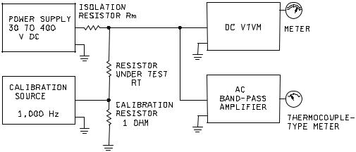
2.1 Test system. The test system shall be as shown in the simplified block diagram on figure 308-1. The dc portion of the system consists of a variable dc power supply and a dc vacuum-tube voltmeter (VTVM). The alternating-current (ac) portion of the system consists of a calibration signal source and an indicating amplifier. The interconnecting leads, as well as the resistor under test, should be adequately shielded.
2.1.1DC measurement considerations. The variable dc power supply furnishes dc loading power through an isolation resistor to the resistor under test. The isolation resistor prevents noise, appearing at the terminals of the resistor under test, from being severely attenuated by the very low, parallel impedance presented by the output terminals of the dc power supply. The isolation resistor must be free of current noise. Quiet wirewound-type resistors are suitable. One of four values for the isolation resistor, Rm, (1,000 ohms, 10,000 ohms, 100,000 ohms, or 1 megohm (mego)) is selected, depending on the resistance of the resistor under test, RT. The dc voltage appearing across the resistor under test is indicated by the dc VTVM. The meter has two scales - one showing the dc voltage across the resistor under test, V, and the other indicating the quantity D-20 log V, in dB. The scale simplifies computation of the current-noise index. The choice of value of the dc voltage is not critical, however, to avoid subjecting the resistor under test, and the isolation resistor as well, to excessive dc power dissipation or voltage, or both, standard nominal values of dc voltage and values for the isolation resistor are given in table 308-1.
2.1.2AC measurement considerations. Noise voltage appearing at the terminals of the resistor under test is amplified and its rms magnitude is shown by the ac indicating amplifier. The indicating amplifier consists of a highgain, low-noise amplifier, a filter, an rms detector, and an output meter. The filter restricts the frequency response of the amplifier to a flat-top, 1,000 Hz pass band, geometrically centered at 1,000 Hz. The output-meter scale, like that of the dc VTVM, is calibrated in dB to simplify calculations.
FIGURE 308-1. Block diagram of system.
METHOD 308
29 November 1961
2