Материал: Стандарт MIL-STD-202G
MIL-STD-202G
METHOD 203C
RANDOM DROP
1.PURPOSE. The random-drop test is used to determine the effects on component parts of random, repeated impact due to handling, shipping, and other field service conditions. The test is an accelerated test designed to indicate structural and mechanical weaknesses of types not necessarily detected in shock and vibration tests.
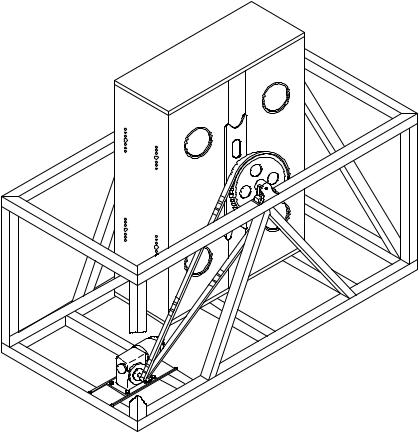
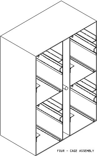
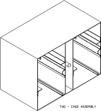
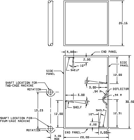
2.APPARATUS. The random-drop test machine consists of an assembly of either two or four steel cages as shown on figure 203-2, with provisions for rotation about a common axis. The interior of each cage shall be as shown on figure 203-3. A typical 4-cage machine is shown on figure 203-1. Steel sleeves as shown on figure 203-4 shall be used to mount the specimen.
3.PROCEDURE. The specimen shall be rigidly mounted by the normal mounting means in the steel sleeve so that no part of the specimen, including terminals or external hardware of the component, will extend beyond the sleeve. When necessary, a suitable adapter may be used within the sleeve. End caps shall not be used on the sleeves. Through bolts may be employed as needed to mount the specimens in the sleeve. Only one sleeve shall be placed in each cage during test. The number of specimens mounted in each sleeve shall be limited only by the available space. Specimens shall be subjected to the random-drop test for a period of 45 minutes at a speed of four to six (4 – 6) revolutions per minute. The machine shall be rotated in the direction shown on figure 203-3.
4.MEASUREMENTS. Upon completion of the test, measurements shall be made as specified in the individual specification.
5.SUMMARY. The following detail shall be specified in the individual specification: a. Measurements after test (see 4).
METHOD 203C
8 February 2002
1 of 6
MIL-STD-202G
FIGURE 203-1. Typical assembly of four-cage random-drop-test machine.
METHOD 203C
8 February 2002
2
MIL-STD-202G
FIGURE 203-2. Cage assembly.
METHOD 203C
8 February 2002
3
MIL-STD-202G
FIGURE 203-2. Cage assembly - Continued.
METHOD 203C
8 February 2002
4
MIL-STD-202G
C
L
Inches |
mm |
Inches |
mm |
Inches |
mm |
.94 |
23.83 |
12.00 |
304.80 |
20.00 |
508.00 |
2.00 |
50.80 |
12.91 |
327.91 |
20.16 |
512.06 |
3.00 |
76.20 |
15.25 |
387.35 |
30.50 |
774.70 |
3.06 |
77.72 |
|
|
|
|
NOTES:
1.Unless otherwise specified, tolerances are ±.06 (1.52 mm) on decimals and ±0° 30' on angles.
2.Material for end and side panels shall be steel .0747 (1.90 mm) nominal thickness.
3.Material for shelves and deflectors shall be steel .083 (2.11 mm) nominal thickness.
FIGURE 203-3. Cage (interior).
METHOD 203C
8 February 2002
5