Материал: Стандарт MIL-STD-202G
MIL-STD-202G
6.SUMMARY. The following details are to be specified in the individual specification:
a.Direction of axis of flame, if other than vertical (see 3).
b.Point of impingement of applied flame (see 3).
c.Time of application of flame, if other than 15 seconds (see 3).
d.Allowable time for burning of visible flame on specimen (see 3).
e.Measurements after test (see 5).
METHOD 111A
16 April 1973
2
MIL-STD-202G
Inches |
mm |
Inches |
mm |
.0004 |
0.01 |
.125 |
3.18 |
.002 |
0.05 |
.127 |
3.23 |
.005 |
0.13 |
.130 |
3.30 |
.006 |
0.15 |
.192 |
4.88 |
.010 |
0.25 |
.194 |
4.93 |
.021 |
0.53 |
.250 |
6.35 |
.041 |
1.04 |
.302 |
7.67 |
.062 |
1.57 |
.322 |
8.18 |
.082 |
2.08 |
.625 |
15.18 |
.120 |
3.05 |
1.688 |
42.88 |
.123 |
3.12 |
|
|
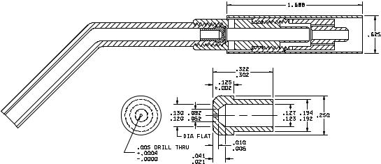
MATERIAL: BRASS
FIGURE 111-1. Burner head.
METHOD 111A
16 April 1973
3
MIL-STD-202G
Inches |
mm |
Inches |
mm |
.003 |
0.08 |
.300 |
7.62 |
.005 |
0.13 |
.470 |
11.94 |
.011 |
0.28 |
.495 |
12.57 |
.039 |
0.99 |
.500 |
12.70 |
.042 |
1.07 |
.562 |
14.27 |
.046 |
1.17 |
.745 |
18.92 |
.170 |
4.32 |
.750 |
19.05 |
.200 |
5.08 |
1.187 |
30.15 |
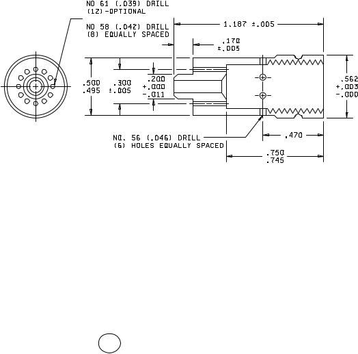
MATERIAL: BRASS
2
BODY-BURNER
FIGURE 111-1. Burner head - Continued.
METHOD 111A
16 April 1973
4
MIL-STD-202G
Inches |
mm |
Inches |
mm |
.002 |
0.05 |
.370 |
9.40 |
.005 |
0.13 |
.375 |
9.53 |
.081 |
2.06 |
.395 |
10.03 |
.090 |
2.29 |
.405 |
10.29 |
.095 |
2.41 |
.430 |
10.92 |
.156 |
3.96 |
.433 |
11.00 |
.187 |
4.75 |
.443 |
11.25 |
.198 |
5.03 |
.500 |
12.70 |
.202 |
5.13 |
.715 |
18.16 |
.250 |
6.35 |
.720 |
18.29 |
.360 |
9.14 |
1.500 |
38.10 |
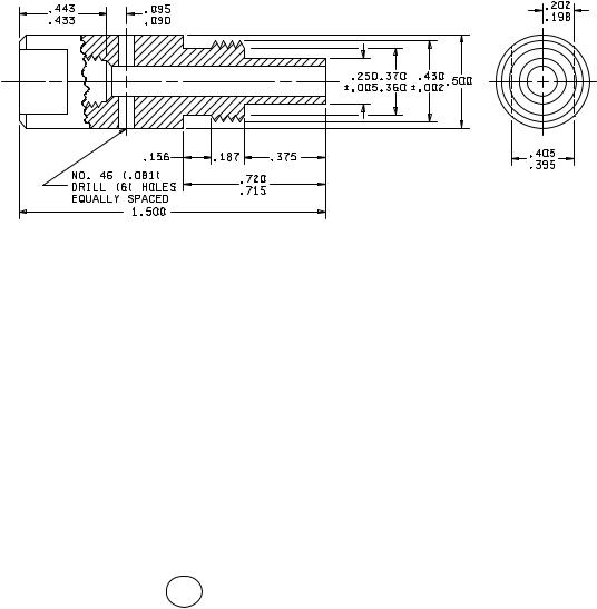
MATERIAL: BRASS
3
BASE-BURNER
FIGURE 111-1. Burner head - Continued.
METHOD 111A
16 April 1973
5