|
DICOM PS3.3 2020a - Information Object Definitions |
Page 1127 |
|
Table C.8.24.2-1. Ultrasound Frame of Reference Module Attributes |
|
Attribute Name |
Tag |
Type |
Attribute Description |
|
Volume Frame of |
(0020,9312) |
1 Uniquely identifies this Volume Frame of Reference. |
|
Reference UID |
|
|
|
|
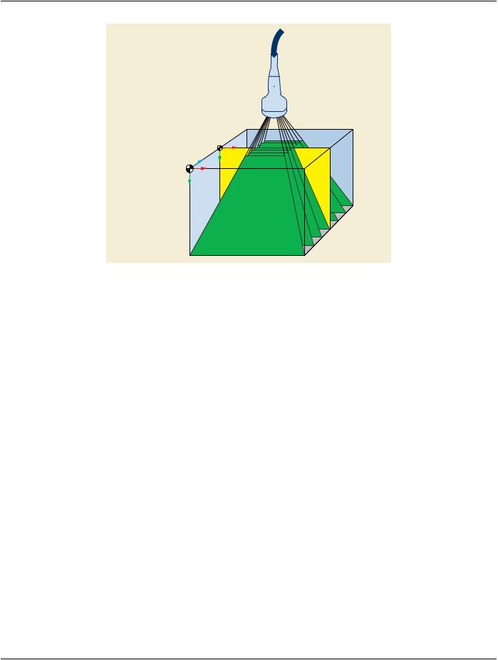
Ultrasound Acquisition(0020,9307) |
1 Characteristic of the ultrasound acquisition geometry. |
|
Geometry |
|
Defined Terms: |
|
|
|
|
|
|
|
|
APEX there exists an apex of the scan lines from which the volume data was |
|
|
acquired. |
|
|
|
PATIENTthe ultrasound acquisition geometry is patient relative |
|
|
|
Note |
|
|
|
|
When the value is PATIENT, the Plane Position (Patient) and Plane |
|
|
Orientation (Patient) Functional Group Macros will be present, and may or |
|
|
may not contain Attributes with identical values to the corresponding |
|
|
Attributes in the Plane Position (Volume) and Plane Orientation (Volume) |
|
|
Functional Group Macros; see Section A.59.4.1.2. |
|
Apex Position |
(0020,9308) |
1C Position of the apex (or phase center) of the acquisition geometry, encoded as xA, |
|
|
yA, and zA in mm units in the Volume Frame of Reference. The apex (xA, yA, zA) may |
|
|
be located in the volume or exterior to it. |
|
|
|
Required if value of Ultrasound Acquisition Geometry (0020,9307) is APEX. |
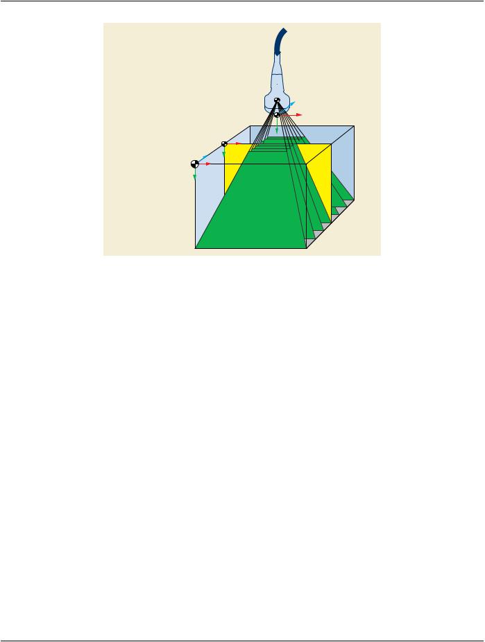
Volume to Transducer(0020,930B) |
1C Relationship between the transducer and the acquired volume. |
|
Relationship |
|
Enumerated Values: |
|
|
|
|
|
|
FIXED |
Thetransducerpositionandorientationrelativetothevolume |
|
|
|
is constant and specified by Volume to Transducer Mapping |
|
|
|
Matrix (0020,9309). |
|
|
|
POSITION_VAR |
The transducer position relative to the volume varies during |
|
|
|
acquisitionandthepositionspecifiedbyVolumetoTransducer |
|
|
|
Mapping Matrix (0020,9309) is a nominal value. The |
|
|
|
transducer orientation relative to the volume is constant and |
|
|
|
specified by Volume to Transducer Mapping Matrix |
|
|
|
(0020,9309). |
|
|
|
ORIENTATION_VARThetransducerorientationrelativetothevolumevariesduring |
|
|
|
acquisition and the orientation specified by Volume to |
|
|
|
Transducer Mapping Matrix (0020,9309) is a nominal value. |
|
|
|
Thetransducerpositionrelativetothevolumeisconstantand |
|
|
|
specified by Volume to Transducer Mapping Matrix |
|
|
|
(0020,9309). |
|
|
|
VARIABLE |
Thetransducerpositionandorientationrelativetothevolume |
|
|
|
varies during acquisition and the position and orientation |
|
|
|
specified by Volume to Transducer Mapping Matrix |
|
|
|
(0020,9309) are nominal. |
|
|
|
Required if the transducer position and/or orientation relative to the volume is not |
|
|
constant. May be present otherwise. |
|
Volume to Transducer(0020,9309) |
1 A 4x4 rigid transformation matrix that maps the Volume Frame of Reference |
Mapping Matrix |
|
homogeneouscoordinatesystem(XV,YV,ZV)totheTransducerFrameofReference |
|
|
homogeneous coordinate system (XX,YX, ZX). Matrix elements shall be listed in |
|
|
row-major order. See Section C.8.24.2.1 for details. |
|