Page 878 |
DICOM PS3.3 2020a - Information Object Definitions |
C.8.11.1.1 DX Series Attribute Descriptions
C.8.11.1.1.1 Presentation Intent Type
Presentation Intent Type (0008,0068) shall identify the intent for the purposes of display or other presentation of all Images within this Series.
Note
1.Since this is a Series level Attribute, all Images within a Series have the same value for this Attribute.
2.The intent of this restriction is to ensure that FOR PRESENTATION and FOR PROCESSING images are placed in separate Series, so that no confusion can arise as to which images are suitable for diagnostic reading as determined by local policy.
A Series of Images intended for viewing by an observer, after application of any grayscale transformations specified in the image object such as VOI LUT, shall have an Enumerated Value of FOR PRESENTATION.
Note
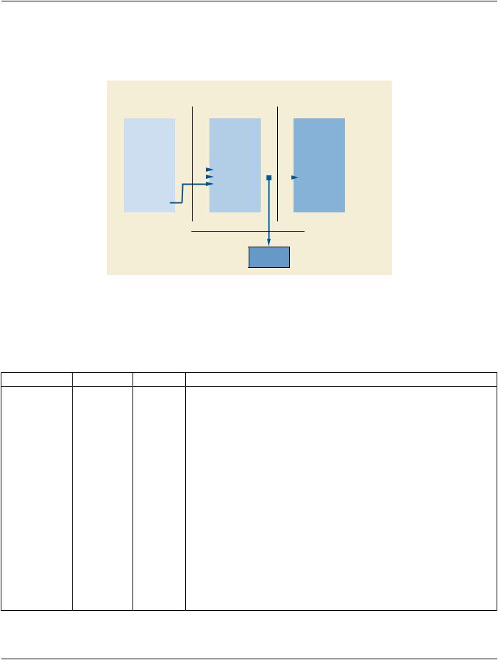
1.These images may still be of Image Type (0008,0008) ORIGINAL rather than DERIVED despite the possibility that they mayhaveundergonesomeprocessing,suchasunsharpmasking.InthiscaseaDERIVEDimagewouldhaveundergone yet further processing to make it substantially different from the original. See Figure C.8-13.
2.These images may still be subjected to processing or further processing, if appropriate, depending on the application.
3.These images are intended for display on a device, without (further) processing, since that device may not be capable of image processing. The quality of the displayed image or its suitability for any purpose is beyond the scope of the DICOM Standard.
Images that have been corrected to account for characteristics of the detector but are intended to be further processed before being displayed, shall have an Enumerated Value of FOR PROCESSING.
Note
This type is provided to allow the functions of image acquisition and image processing for presentation to be separated and yet have images conveyed between the two processes using a DICOM object. Individual sites or users may choose to sub- stitute their own specialized processing in place of that supplied by the implementer.
Images available at this stage of processing may be useful for quality control and problem solving purposes, as well as academic research.
Images of this type may also be archived, retrieved and processed with different algorithms or parameters in order to alter the appear- ance of specific features for clinical purposes.
ThenatureofthedetectorcorrectionthatmayhavebeenappliedbeforesendinganimageoftypeFORPROCESSINGisnotspecified. In particular, acquisitions that acquire several sets of matrices of pixel values (such as image data, gain offset and a defect map) must perform some processing (detector correction) before a DX Image object can be instantiated.
ThenatureoftheprocessingthatmayhavebeenappliedbeforesendinganimageoftypeFORPRESENTATIONisalsonotspecified.
It is expected that individual implementers will use Private Attributes to convey specifics of the processing applied that may be of use for further processing by those aware of the parameters and algorithms. The diversity of detector types and processing algorithms make it undesirable to standardize such parameters.
Whether or not the spatial locations of all pixels are preserved during the processing of the source image that resulted in the current image can be indicated by Spatial Locations Preserved (0028,135A) in a Source Image Sequence (0008,2112) reference from the FOR PRESENTATION image to a FOR PROCESSING predecessor.
If images from the same exposure exist with different Values of Presentation Intent Type (0008,0068), then they shall have different SOP Instance UIDs.