Материал: part03

Внимание! Если размещение файла нарушает Ваши авторские права, то обязательно сообщите нам

Page 676​

DICOM PS3.3 2020a - Information Object Definitions​

For example: Some Ultrasound images may have a Photometric Interpretation equal to RGB but the image will have no​ color information if R=G=B for all pixels.​

For consistency within a particular implementation Monochrome Ultrasound images may be coded using a color photometric​ interpretation. In that case inclusion of this Attribute can significantly speed up processing. Since all components are known​ tobeequalonlyoneneedbehandled.TheenhancementscanbesignificantwhencompressedTransferSyntaxesareused.​

C.8.5.6.1.11 Overlay Subtype​

Defined Terms:​

ACTIVE 2D/BMODE IMAGE​ identification of the active area of a 2D/B-mode image​

AREA​

C.8.5.6.1.12 Samples Per Pixel​

For US Images, Samples Per Pixel (0028,0002) is specified to use the following values for specific Photometric Interpretations:​

Table C.8-19. US Samples Per Pixel​

Photometric Interpretation​

Samples Per Pixel Value​

MONOCHROME2​

1​

RGB​

3​

YBR_FULL​

3​

YBR_FULL_422​

3​

YBR_RCT​

3​

YBR_ICT​

3​

YBR_PARTIAL_420​

3​

PALETTE COLOR​

1​

C.8.5.6.1.13 Bits Allocated​

For US Images, Bits Allocated (0028,0100) is specified to use the following values for specific Photometric Interpretations:​

Table C.8-20. US Bits Allocated​

Photometric Interpretation​

Bits Allocated Value​

MONOCHROME2​

8​

RGB​

8​

YBR_FULL​

8​

YBR_FULL_422​

8​

YBR_RCT​

8​

YBR_ICT​

8​

YBR_PARTIAL_420​

8​

PALETTE COLOR​

8 - 8 bit palette, or​


16 - 16 bit palette​

C.8.5.6.1.14 Bits Stored​

For US Images, Bits Stored (0028,0101) shall be equal to Bits Allocated (0028,0100).​

C.8.5.6.1.15 High Bit​

For US Images, High Bit (0028,0102) shall be one less than Bits Stored (0028,0101).​

- Standard -​

DICOM PS3.3 2020a - Information Object Definitions​

Page 677​

C.8.5.6.1.16 Planar Configuration​

For US Images, Planar Configuration (0028,0006) is specified to use the following values for specific Photometric Interpretations:​

Table C.8-23. US Planar Configuration​

Photometric Interpretation​

Planar Configuration Value​

RGB​

0 - color-by-pixel, or​


1 - color-by-plane​

YBR_FULL​

0 or 1 if uncompressed​


0 if lossless JPEG, lossless JPEG-LS or reversible JPEG 2000​


1 if RLE​

YBR_FULL_422​

0​

YBR_RCT​

0​

YBR_ICT​

0​

YBR_PARTIAL_420​

0​

C.8.5.6.1.19 View Code Sequence​


The view of the patient anatomy may be described using coded terminology in the View Code Sequence (0054,0220). The view is​ typically specified by transducer position relative to the patient anatomy and/or transducer orientation,​

The view may be described by a single Code Sequence Item, or by combination of post-coordinated Code Sequence Items. The​ principalcodeisspecifiedinViewCodeSequence,andmodifiertermsintheViewModifierCodeSequence(0054,0222).TheBaseline​ CIDs for post-coordinated encoding of view are:​

•​CID 4 “Anatomic Region” (typically used for the primary coded item)​

•​CID 5 “Transducer Approach”​

•​CID 6 “Transducer Orientation”​

•​CID 7 “Ultrasound Beam Path”​

Any of these Context Groups may be used in either the View Code Sequence or the View Modifier Code Sequence.​

For cardiac imaging, a Baseline CID with pre-coordinated view codes is specified:​

•​CID 12226 “Echocardiography Image View”​

Note​

Transducer Position Sequence (0008,2240) and Transducer Orientation Sequence (0008,2244), defined in this Module in​ an earlier edition of the Standard (see PS3.3-2004), are retired.​

C.8.5.6.1.20 (Retired)​

C.8.5.6.1.21 IVUS Acquisition​

Defined Terms:​

MOTOR_PULLBACK​TheIVUSimagingcatheterispositionedinthebloodvesselunderexaminationdistaltotheanatomicalstructures​ to be examined. Then the catheter is attached to a motorized mechanism capable of withdrawing the catheter​ through the vessel at a constant velocity specified by the Attribute IVUS Pullback Rate (0018,3101) from the​ defined IVUS Pullback Start Frame Number (0018,3103) (see Section C.8.5.6.1.24) to the IVUS Pullback Stop​ Frame Number (0018,3104) (see Section C.8.5.6.1.25).​

MANUAL_PULLBACK​TheIVUSimagingcatheterispositionedinthebloodvesselunderexaminationdistaltotheanatomicalstructures​ to be examined. Then the catheter is manually withdrawn through the vessel region of interest.​

- Standard -​

Page 678​

DICOM PS3.3 2020a - Information Object Definitions​

SELECTIVE​

The IVUS imaging catheter is positioned in the blood vessel under examination near the anatomical structures​

to be examined. Then the catheter is manually withdrawn or advanced through the vessel region of interest.​ GATED_PULLBACK​TheIVUSimagingcatheterispositionedinthebloodvesselunderexaminationdistaltotheanatomicalstructures​ to be examined. Then the catheter is attached to a motorized mechanism capable of withdrawing the catheter​ through the vessel at a rate specified by the Attribute IVUS Gated Rate (0018,3102), once per heart cycle,​ from the defined IVUS Pullback Start Frame Number (0018,3103) (see Section C.8.5.6.1.24) to the IVUS​

Pullback Stop Frame Number (0018,3104) (see Section C.8.5.6.1.25).​

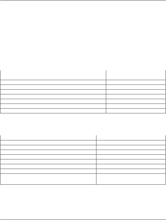
C.8.5.6.1.22 IVUS Pullback Rate​

TheAttributeIVUSPullbackRate(0018,3101)isrequiredwhenIVUSAcquisition(0018,3100)isMOTOR_PULLBACKanditspecifies​ the velocity of withdrawal of the IVUS imaging catheter in millimeters per second.​

C.8.5.6.1.23 IVUS Gated Rate​

The Attribute IVUS Gated Rate (0018,3102) is required when IVUS Acquisition (0018,3100) is GATED_PULLBACK and it specifies​ the velocity of withdrawal of the IVUS imaging catheter in millimeters per beat.​

C.8.5.6.1.24 IVUS Pullback Start Frame Number​

The IVUS Pullback Start Frame Number (0018,3103) specifies the frame number of a IVUS multi-frame acquisition upon which mo-​ torized or gated pullback begins.​

C.8.5.6.1.25 IVUS Pullback Stop Frame Number​

The IVUS Pullback Stop Frame Number (0018,3104) specifies the frame number of a IVUS multi-frame acquisition upon which mo-​ torized or gated pullback ends.​

C.8.5.6.1.26 Lesion Number​

Attribute Lesion Number identifies the lesion(s) of interest imaged within the current SOP Instance. Each lesion shall have a unique​ numeric integer identifier within the Study. If during a Study the same lesion is imaged more than once, the same Lesion Number​ should be used for both SOP Instances.​

Note​

1.​Lesion Number is not a DICOM UID.​

2.​An IVUS pullback may contain multiple values in Lesion Number.​

C.8.6 Secondary Capture Modules​

C.8.6.1 SC Equipment Module​

This Module describes equipment used to convert images into a DICOM format.​

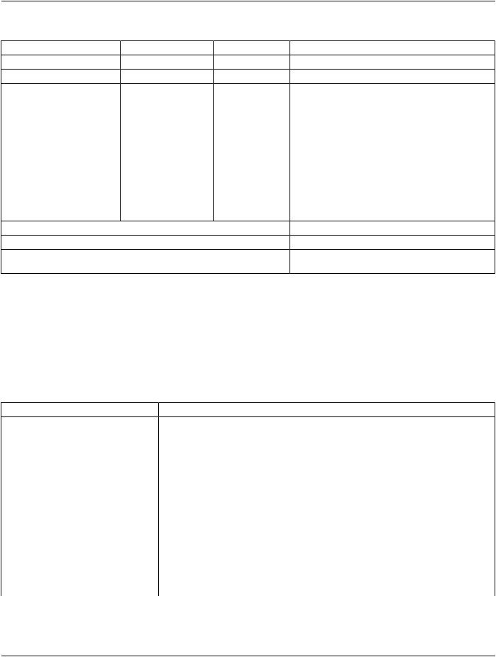
Table C.8-24. SC Equipment Module Attributes​

Attribute Name​

Tag​

Type​

Attribute Description​

Conversion Type​

(0008,0064)​

1​ Describes the kind of image conversion.​

Defined Terms:​

DV​ Digitized Video​

DI​ Digital Interface​

DF​ Digitized Film​

WSD​Workstation​

SD​ Scanned Document​

SI​ Scanned Image​

DRW​Drawing​

SYN​Synthetic Image​

- Standard -​


DICOM PS3.3 2020a - Information Object Definitions​

Page 679​

Attribute Name​

Tag​

Type​

Attribute Description​


Modality​

(0008,0060)​

3​ Source equipment for the image. This type definition shall​


override the definition in the General Series Module.​


See Section C.7.3.1.1.1 for Defined Terms.​


Secondary Capture Device ID​

(0018,1010)​

3​ User defined identification of the device that converted the​


image​


Secondary Capture Device​

(0018,1016)​

3​ Manufacturer of the Secondary Capture Device​


Manufacturer​


Secondary Capture Device​

(0018,1018)​

3​ Manufacturer's model number of the Secondary Capture​

Manufacturer's Model Name​


Device​


SecondaryCaptureDeviceSoftware​

(0018,1019)​

3​ Manufacturer's designation of software version of the​

Versions​


Secondary Capture Device​


Video Image Format Acquired​

(0018,1022)​

3​ Originalformatofthecapturedvideoimage(e.g.,NTSC,PAL,​


Videomed-H)​


Digital Image Format Acquired​

(0018,1023)​

3​ Additional information about digital interface used to acquire​


the image​


Note​

1.​The Attributes specified in the General Equipment Module (see Table C.7-8) describe the equipment that created the​ image being captured. The Attributes of the SC Equipment Module define the equipment that captured the image. The​ following table illustrates typical scenarios for different conversion types:​

Conversion Type​

General Equipment​

Secondary Capture Equipment​

(0008,0064)​


Digitized Video (DV)​

The equipment generating the video signal.​The equipment digitizing the video signal.​

Digital Interface (DI)​

The equipment on the sending side of the​

The equipment on the receiving side of the​


digital interface.​

digital interface.​

Digitized Film (DF)​

The equipment that created the film.​

The equipment digitizing the film.​

Workstation (WSD)​

Application dependent, but often the​

The equipment that captured the image​


equipment that placed the image on the​

from the screen, or placed the modified​


workstation screen, or created the modified​image into a DICOM SOP Instance.​


image.​


Scanned Document (SD)​

The equipment that created the document.​ The equipment digitizing the document.​

Scanned Image (SI)​

The equipment that created the image that​ The equipment digitizing the image.​


was digitized.​


Drawing (DRW)​

The equipment that created the drawing.​

Theequipmentdigitizing(orrasterizing)the​


drawing.​

Synthetic Image (SYN)​

The equipment creating the original images​The equipment creating the synthetic​


from which the synthetic image was derived.​image.​

2.​Modality (0008,0060) specified in the General Series Module (see Table C.7-5a) has been specialized by this Module​ and is defined as a Type 3 Attribute.​

C.8.6.2 SC Image Module​

Table C.8-25 contains IOD Attributes that describe Secondary Capture Images.​

- Standard -​

Page 680​ DICOM PS3.3 2020a - Information Object Definitions​

Table C.8-25. SC Image Module Attributes​

Attribute Name​

Tag​

Type​

Attribute Description​

Date of Secondary Capture​

(0018,1012)​

3​

ThedatetheSecondaryCaptureImagewascaptured.​

Time of Secondary Capture​

(0018,1014)​

3​

The time the Secondary Capture Image was captured.​

Nominal Scanned Pixel​

(0018,2010)​

3​

Physical distance on the media being digitized or​

Spacing​


scanned between the center of each pixel, specified​


by a numeric pair - adjacent row spacing (delimiter)​


adjacent column spacing in mm. See Section 10.7.1.3​


for further explanation of the value order.​


ShallbeconsistentwithPixelAspectRatio(0028,0034),​


if present.​

Document Class Code​

(0040,E008)​

3​

Classifications of a scanned document, e.g., for​

Sequence​


Modality (0008,0060) DOC. Equivalent to HL7 v2.x​


TXA-2.​


One or more Items are permitted in this Sequence.​

>Include Table 8.8-1 “Code Sequence Macro Attributes”​


No Baseline CID is defined.​

Include Table 10-10 “Basic Pixel Spacing Calibration Macro Attributes”​


Include Table 10-25 “Optional View and Slice Progression Direction Macro​

Attributes”​

Note​

The Attributes specified in the General Image Module (see Table C.7-7) describe this image (i.e., the secondary capture​ image). For example, Instance Number (0020,0013) is the image number of the secondary capture image. Source Image​ Sequence (0008,2112) may reference the DICOM image from which this image was generated.​

C.8.6.3 SC Multi-frame Image Module​

Table C.8-25b contains IOD Attributes that describe SC Multi-frame images.​

Table C.8-25b. SC Multi-frame Image Module Attributes​

Attribute Name​

Tag​

Type​

Attribute Description​

Burned In Annotation​

(0028,0301)​

1​ Indicates whether or not image contains sufficient burned in annotation to​


identify the patient and date the image was acquired.​


Enumerated Values:​


YES​


NO​

Recognizable Visual​

(0028,0302)​

3​ Indicates whether or not the image contains sufficiently recognizable visual​

Features​


features to allow the image or a reconstruction from a set of images to identify​


the patient.​

Enumerated Values:​

YES​

NO​

If this Attribute is absent, then the image may or may not contain recognizable​ visual features.​

- Standard -​