Page 664 |
DICOM PS3.3 2020a - Information Object Definitions |
C.8.5.5.1.10 TM-line Position X0, Y0, X1 and Y1
The TM-Line Position X0 (0018,603D) and TM-Line Position Y0 (0018,603F) are the coordinates of the starting point and TM-Line Position X1 (0018,6041), TM-Line Position Y1 (0018,6043) are the coordinates of the end point of the TM-line. The coordinate is defined as the displacement, in pixels, from the Reference pixel. Typically used for M-mode line and CW Doppler.
C.8.5.5.1.11 Number of Table Entries
The Number of Table Entries (0018,6056) gives the number of entries in the Table of Pixel Values, the number of entries in the Table of Parameter Values (0018,605A), if present, and the number of Items in the Pixel Value Mapping Code Sequence (0040,9098), if present.
C.8.5.5.1.12 Table of Pixel Values
The Table of Pixel Values (0018,6058) specifies the pixel values that are mapped to real world parameter values or coded concepts (tissue characterizations). The number of entries in the table is given by Number of Table Entries (0018,6056).
A pixel is calibrated (mapped to a real-world value) by finding an entry in the Table of Pixel Values that matches its Composite Pixel Code (see Section C.7.6.3.1.1). The offset index of this entry is used as an index into the Parameter Value Table (0018,605A) or as a Sequence Item number in the Pixel Value Mapping Code Sequence (0040,9098) to select the real world value. The first Table of Pixel Values entry corresponds to Sequence Item 1.
Note
If a Composite Pixel Code has no matching value in the Pixel Value Table then there is no unambiguous way to determine the corresponding Parameter Value. A method may exist to determine a valid Parameter Value but the specification of such a method is outside the scope of the DICOM Standard. No assumption should be made that linear interpolation will produce a valid result.
C.8.5.5.1.13 Table of Parameter Values
The Table of Parameter Values (0018,605A) provides the real world values for pixel values identified in the Table of Pixel Values (0018,6058). The number of table entries is given by Number of Table Entries (0018,6056) and the physical units are given by Pixel Component Physical Units (0018,604C). Values may repeat when a parameter value is associated with more than one Composite Pixel Code value.
C.8.5.5.1.14 Region Location Min X0, Min Y0, Max X1 and Max Y1
TheseAttributesspecifythelocationoftheregion,RegionLocationMinX0(0018,6018),RegionLocationMinY0(0018,601A),Region Location Max X1 (0018,601C), Region Location Max Y1 (0018,601E) expressed as offsets to the pixel coordinates. The upper left corner of the entire image is x=0,y=0 and the lower right corner is x=image width - 1, and y=image length - 1. Thus, a region will be specified as within these bounds. Where x0,y0 is the coordinate of the upper left corner of the region and x1,y1 is the coordinate of the lower right corner of the region.
C.8.5.5.1.15 Physical Units X Direction and Physical Units Y Direction
Physical Units X Direction (0018,6024) and Physical Units Y Direction (0018,6026) indicate the physical units of the dimensions of the region.
Enumerated Values:
0000HNone or not applicable 0001HPercent
0002HdB 0003Hcm
0004Hseconds 0005Hhertz(seconds-1) 0006HdB/seconds
0007Hcm/sec
0008Hcm2
0009Hcm2/sec
000AHcm3
000BHcm3/sec


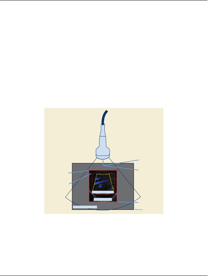

 x1, y1 = (436,345)