Page 652 |
DICOM PS3.3 2020a - Information Object Definitions |
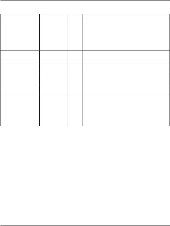
Attribute Name |
Tag |
Type |
Attribute Description |
>Data Information |
(0054,0063) |
2 |
Sequence of Items that describe gating criteria. |
Sequence |
|
|
Zero or more Items shall be included in this Sequence. |
|
|
|
|
|
|
See Section C.8.4.13.1.1. |
>>Frame Time |
(0018,1063) |
1 |
Nominal time per individual frame in msec. |
>>Nominal Interval |
(0018,1062) |
3 |
Average duration of accepted beats, in msec. |
>>Low R-R Value |
(0018,1081) |
3 |
R-R interval lower limit for beat rejection, in msec |
>>High R-R Value |
(0018,1082) |
3 |
R-R interval upper limit for beat rejection, in msec |
>>Intervals Acquired |
(0018,1083) |
3 |
Number of heartbeats that fall within Low R-R Value (0018,1081) and |
|
|
|
HighR-RValue(0018,1082),andwerethereforeacceptedandcontribute |
|
|
|
gamma events to this R-R Interval. |
>>Intervals Rejected |
(0018,1084) |
3 |
Number of heartbeats that fall outside Low R-R (0018,1081) and High |
|
|
|
R-R Value (0018,1082), and do not contribute gamma events to this |
|
|
|
R-RInterval.However,theymaycontributegammaeventstootherR-R |
|
|
|
Intervals. |
>>Time Slot Information |
(0054,0072) |
2C |
Sequence of Items that describe Time Slot Information. Required if the |
Sequence |
|
|
Frame Increment Pointer (0028,0009) contains the Tag for Time Slot |
|
|
|
Vector (0054,0070). |
|
|
|
Zero or more Items shall be included in this Sequence. |
|
|
|
The number of Items shall be equal to Number of Time Slots |
|
|
|
(0054,0071). The first Item corresponds to frames with value of 1 in the |
|
|
|
Time Slot Vector (0054,0070), the second Item with value 2, etc. |
>>>Time Slot Time |
(0054,0073) |
3 |
The total amount of time, in msec, that the acquisition accumulates |
|
|
|
gamma events into this frame. See Section C.8.4.13.1.2. |
C.8.4.13.1 NM Multi-gated Acquisition Attribute Descriptions
C.8.4.13.1.1 Data Information Sequence
Data Information Sequence (0054,0063) shall contain a single Item that applies to the sum of all angular views, except when Image Type (0008,0008) Value 3 is GATED TOMO. In this case it shall have either a single Item that applies to the sum of all angular views, or it shall have one Item for each angular view.
C.8.4.13.1.2 Time Slot Time
The Time Slot Time (0054,0073) records the effective imaging time of each Time Slot. For example, if some of the accepted beats are shorter than others then the last frames may not receive a contribution from the shorter beats. The Time Slot Time for a Time Slot is the total acquisition time for that Time Slot. It is approximately equal to Frame Time (0018,1063) multiplied by the number of accepted beats contributing to the Time Slot.
C.8.4.14 NM Phase Module
Table C.8-14 contains Attributes that describe dynamic phases of a dynamic acquisition image performed on the patient. This Module is present only when Image Type (0008,0008), Value 3, is equal to DYNAMIC. A phase is defined as a collection of frames in which the acquisition time per frame and the time delay between frames remains constant. A new phase shall be defined whenever there is a change in the time between frames, the acquisition time per frame, or the position of the patient relative to the detector.