Материал: m912201e
Visualization • 249
Create Visualization
8.2.2.2 Modifying Visualization Elements
You can select an element which has already been inserted by a mouse click on the element or by pressing the <tab> key. A small black square will appear at each corner of each of the elements, (with ellipses at the corners of the surrounding rectangle). Except in the case of polygons, lines or curves further squares appear in the middle of the element edges between the corner points.
With a selected element, the turning point (balance point) is also displayed at the same time. You can then rotate the element around this point with a set motion/angle. The turning point is displayed as a small black circle with a
white cross ( ). You can drag the turning point with a pressed left mouse button.
You can change the size of the element by clicking on one of the black squares and, while keeping the left mouse button pressed, controlling the new outline.
With the selection of a polygon, you can drag each individual corner using the same technique. While doing this, if you press the <Ctrl>-key then an additional corner point will be inserted at the corner point, an additional corner point will be inserted, which can be dragged by moving the mouse. By pressing the <Shift>+<Ctrl>-key, you can remove a corner point.
8.2.2.3 Dragging Visualization Elements
One or more selected elements can be dragged by pressing the left mouse button or the arrow key.
8.2.2.4 Copying Visual Elements
One or more selected elements can be inserted with the 'Edit' 'Copy'command, the <Ctrl>+<C> key combination, or the corresponding copy symbol, and with 'Edit' 'Paste'.
A further possibility is to select the elements and to again click in one of these elements with the <Ctrl> key held down. If you now hold the left mouse button down, you can separate the elements thus copied from the original.
8.2.2.5 Changing the Selection and Insert Mode
After the insertion of a visualization element, there is an automatic change back into the selection mode. If you want to insert an additional element the same way, you can once again select the corresponding command in the menu
or the symbol  in the tool bar.
WAGO-I/O-SYSTEM 759 WAGO-I/O-PRO 32

250 • Visualization
Create Visualization
You can also quickly change between the selection mode and the insert mode by pressing the <Ctrl>-key and the right mouse button simultaneously.
In the insert mode, the corresponding symbol will also appear at the mouse pointer, and the name will also be indicated in black in the status bar.
8.2.2.6 Status Bar in the Visualization
If a visualization has the focus, the current X and Y position of the mouse cursor in pixels relative to the upper left corner of the image is displayed in the status bar. If the mouse pointer is located on an Element, or if the element is being processed, then the number of the element will be displayed. If you have selected an element to insert, then this element will also appear (for example,
Rectangle).
8.2.3 Visualization Elements, Configure
8.2.3.1 'Extras' 'Configure'
With this command, the 'Configure element' dialog opens for configuring the selected visualization element (see Select visualization element). You are given the dialog box when you doubleclick on the element.
Select a category in the left area of the dialog box, and fill out the requested information in the right area.
Depending on the visualization element selected, various categories can be selected:
Shape |
Rectangle, Rounded Rectangle, Ellipse |
Text |
All |
Color |
Rectangle, Rounded Rectangle, Ellipse, Polygon, |
|
Line, Curve |
Motion absolute |
All |
Motion relative |
All, except Polygon, Line, Curve |
Variables |
All |
Input |
All |
Tooltip |
All |
Bitmap |
Bitmap, Button |
Visualization |
Visualization |
At locations in the element configuration where program variables are operative, the following Entries are possible:
WAGO-I/O-SYSTEM 759 WAGO-I/O-PRO 32

Visualization • 251
Create Visualization
Variable names, for which input assistant is available
Expressions which are assembled from component accesses, field accesses with constant index, variables and direct addresses.
Operators and constants, which can be combined at will with the aforementioned expressions.
Examples of permissible expressions:
x + y 100*PLC_PRG.a TRUE
NOT PLC_PRG.b
9*sin(x + 100)+cos(y+100)
Function calls are not possible. Invalid expressions result in an error message on login ("Invalid Watch expression..."). Examples of invalid expressions: fun(88), a := 9, RETURN.
There are two possible ways to write global variables: ".globvar" and "globvar" are equivalent. The style with a dot is not possible within an assembled expression, however.
See also below for the possible use of Placeholders.
8.2.3.2 Placeholder
At each location in the configuration dialog at which variables or text are entered, a placeholder can be set in place of the respective variable or text. This makes sense if the visualization object is not to be used directly in the program, but is created to be inserted in other visualization objects as a reference. When configuring such a Reference, the placeholders can be replaced with variable names or with text (see "Configuring an inserted visualization"). Any text enclosed in two dollar signs ($) is a valid placeholder (e.g. $variable1$, variable$x$). For each placeholder, a "value group" can be defined as an input specification in the 'Placeholder list' dialog (called from 'Extras' 'Placeholder list').
8.2.3.3 'Extras' 'Placeholder list'
This dialog applies to the visualization object that has the input focus. It displays the placeholders set in that object and allows prior definition of what values each placeholder can be replaced with when configuring a reference of this visualization (see 'Visualization').
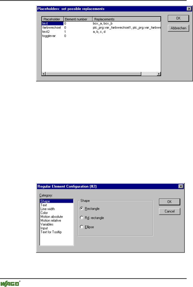
x Placeholder list for input of possible replacements for the placeholders
WAGO-I/O-SYSTEM 759 WAGO-I/O-PRO 32
252 • Visualization
Create Visualization
All placeholders provided for in the visualization are listed in the Placeholder column. The Element number column shows in which element a placeholder has been configured. A selection of strings, which can then be used as input in a reference in place of the placeholder, can be entered for these placeholders in the Replacements column. The elements of the selection must be entered separated by commas. If an impossible replacement string is specified, then the placeholder can be replaced with any desired text when configuring the reference that contains it.
8.2.3.4 Shape
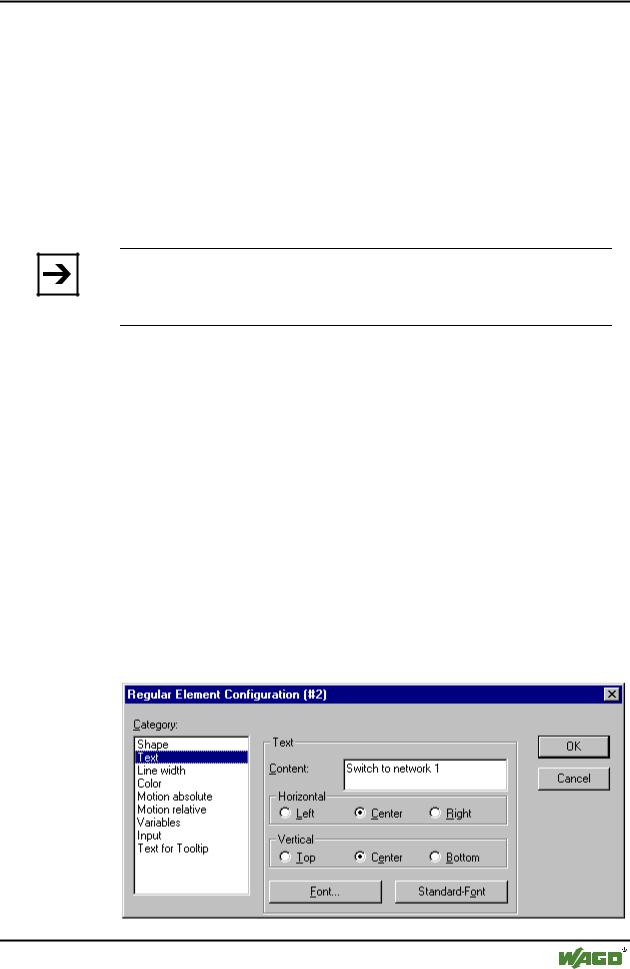
In the visualization element configuration dialog box, you can select in the
Shape category from among Rectangle, Rounded Rectangle, and Ellipse respectively Polygon, Line and Curve. The form will change into the size already set.
x Dialog Box for Configuring Visualization Elements (Shape Category)
WAGO-I/O-SYSTEM 759 WAGO-I/O-PRO 32
Visualization • 253
Create Visualization
8.2.3.5 Text
In the dialog for configuring visualization elements, you can specify a text for the element in the Text category, which can be entered directly or represented by a placeholder.
Enter the text in the Content field. With the key combination <Crtl>+<Enter> you can insert line breaks, with <Crtl>+<Tab>, tab stops.
If you enter "<name>" into the text, then this location, in Online mode, will be replaced by the value of the variable from the Text Output field of the
Variables category.
Note:
If a text string is to be transferred into a translation file, which will then be used in Online mode to enable switching into another national language, it must be delimited at the beginning and end by #.
Examples: "#Pump 1#" or else even "#Pump# 1"
The second case might for example, in the event of multiple occurrences of the text Pump (Pump 1, Pump 2, etc.), prevent multiple appearances in the translation.
The configured text will appear online in the prescribed alignment within the element: horizontally left, center or right and vertically top, center or bottom.
If you use the Font button, a dialog box for selection of the font will appear. Select the desired font and confirm the dialog with OK. With the StandardFont button you can set the font that is selected in the project options ('Project' 'Options' 'Editor'). If the font is changed there, then this font will be displayed in all elements except in those elements for which another font has explicitly been selected by using the Font button.
x Dialog Box for Configuring Visualization Elements (Text Category)
WAGO-I/O-SYSTEM 759 WAGO-I/O-PRO 32