Материал: m912201e
Visualization • 259
Create Visualization
8.2.3.12ToolTip
The dialog Text for Tooltip offers an input field for text which appears in a text field as soon as the mouse cursor is passed over the object in online mode. The text can be formatted with line breaks by using the key combination <Ctrl> + <Enter>.
8.2.3.13Bitmap
You can enter the options for a bitmap in the Bitmap category within the visualization element configuration dialog box.
Enter the bitmap file and its path in the Bitmap field. You can use the ... button to open the standard Windows Browse dialog box from which you can select the desired bitmap.
All other entries affect the frame of the bitmap.
By selecting Anisotropic, Isotropic or Fixed you specify how the bitmap should react to changes in the size of the frame. Anisotropic means that the bitmap remains the same size as the frame which allows you to change the height and width of the bitmap independently. Isotropic means that the bitmap retains the same proportions even if the overall size is changed (i.e., the relationship between height and width is maintained). If Fixed is selected, the original size of the bitmap will be maintained regardless of the size of the frame.
If the Clip option is selected together with the Fixed setting, only that portion of the bitmap that is contained within the frame will be displayed.
If you select the Draw option, the frame will be displayed in the color selected in the Color and Alarm color buttons in the color dialog boxes. The alarm color will only be used if the variable in the Change Color field in the Variable category is TRUE.
x Visualization Element Configuration Dialog Box (Bitmap Category)
WAGO-I/O-SYSTEM 759 WAGO-I/O-PRO 32

260 • Visualization
Create Visualization
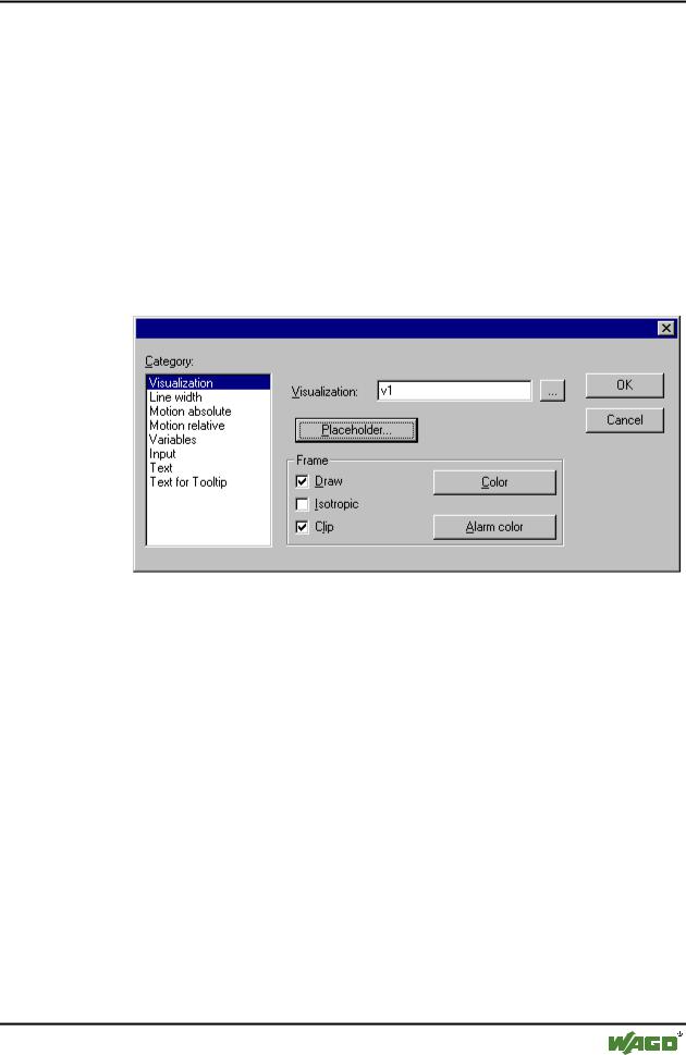
8.2.3.14Visualization
You can enter the options for a visualization as an element in another visualization in the Visualization category within the visualization element configuration dialog box. Enter the object name for the visualization in the Visualization field. Use the ... button to open a dialog box containing the visualizations available in this project. Any visualization may be used with the exception of the current one.
All other entries affect the visualization frame.
If you select the Draw option, the frame will be displayed in the color selected in the Color and Alarm color buttons in the color dialog boxes. The alarm color will only be used if the variable in the Change Color field in the Variables category is TRUE.
If Isotropic is selected, the proportions of the visualization will be maintained even if the size changes (i.e., the relationship between height and width will remain the same). Otherwise the proportions can be changed.
If the Clip option is selected in Online mode, only the original portion of the visualization will be displayed. For example, if an object extends beyond the original display area, it will be clipped and may disappear from view completely in the visualization.
The Placeholder button leads to the 'Replace placeholder' dialog. It lists in the 'Placeholder' column all the placeholders used in the inserted visualization POU and offers in the 'Replacements' column the possibility of replacing these with a definite value. Which replacements are possible in a given case depends on whether a value group was predefined in the 'Extras' 'Placeholder list' dialog. If this is the case, it will be displayed in a combo box for selection. If nothing was pre-defined, double clicking on the corresponding field in the Replacements column opens an editing field which can be filled in as desired.
A further possibility for replacing placeholders in references occurs directly during the calling of a visualization, by entry into the Zoom to vis. option field in the 'Input' category of the configuration dialog for a visualization element.
Note:
No control of the chronological sequence of replacements is possible! Therefore no placeholders should be replaced with text that also contains placeholders!
Note:
When using placeholders it is no longer possible to check for invalid entries in the configuration of the visualization element immediately upon compilation of the project. Hence the appropriate error messages are first issued in Online mode (...Invalid Watch expression..).
WAGO-I/O-SYSTEM 759 WAGO-I/O-PRO 32
Visualization • 261
Create Visualization
Example of an application of the placeholder concept:
Instances of a function block can easily be displayed with the help of references of the same visualization. For example, in configuring the visualization visu, which visualizes the variables of function block fu, one could begin each variable entry with the placeholder $FUB$ (e.g. $FUB$.a). If a reference from visu is then used (by inserting visu in another visualization or by calling via 'Zoom to vis.'), then in the configuration of this reference the placeholder $FUB$ can then be replaced with the name of the function block fu instance to be visualized (for example $FUB$ -> PLC_PRG.inst_1). In another reference of visu, $FUB$ could be replaced with another instance of fu.
x Visualization Element Configuration Dialog Box (Visualization Category)
8.2.4 Additional Visualization Element Functions
8.2.4.1 'Extras' 'Send to Front'
Use this command to bring selected visualization elements to the front.
8.2.4.2 'Extras' 'Send to Back'
Use this command to send selected visualization elements to the back.
8.2.4.3 'Extras' 'Select Background Bitmap'
Use this command to open the dialog box for selecting files. Select a file with the extension "*.bmp". The selected bitmap will then appear as the background in your visualization.
The bitmap can be removed with the command 'Extras' 'Clear Background Bitmap'.
WAGO-I/O-SYSTEM 759 WAGO-I/O-PRO 32

262 • Visualization
Create Visualization
8.2.4.4 'Extras' 'Clear Background Bitmap'
Use this command to remove the bitmap as the background for the current visualization.
You can use the command 'Extras' 'Select Background Bitmap' to select a bitmap for the current visualization.
8.2.4.5 'Extras' 'Align'
Use this command to align selected visualization elements.
The following alignment options are available:
Left: the left edge of each of the elements will be aligned to the element that is furthest to the left
the same is true for Right / Top / Bottom
Horizontal Center: each of the elements will be aligned to the average horizontal center of all elements
Vertical Center: each of the elements will be aligned to the average vertical center of all elements
8.2.4.6'Extras' 'Select All'
This command allows you to select all visualization elements within the current visualization object.
8.2.4.7 'Extras' 'Select Mode'
This command is used to switch the selection mode on or off. This can also be
achieved using the symbol  or by pressing the right mousekey while holding down the <Ctrl> key at the same time.
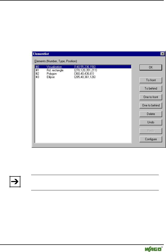
8.2.4.8 'Extras' 'Element list'
This command opens a dialog box containing a list of all visualization elements including their number, type and position. The position is given according to the x and y position of the upper left and lower right corner of the element.
When one or more items have been selected, the corresponding elements in the visualization are marked for visual control and if necessary the display will scroll to that section of the visualization that contains the elements.
Use the To front button to bring selected visualization elements to the front. Use the To behind button to move them to the back.
Use the Delete button to remove selected visualization elements.
WAGO-I/O-SYSTEM 759 WAGO-I/O-PRO 32
Visualization • 263
Create Visualization
Use the Undo and Redo buttons to undo or restore changes that have been made just as you would do with the commands 'Edit' 'Undo' and 'Edit' 'Redo' . In the dialog box, you can observe the changes that are being made.
Click on OK to close the dialog box and confirm the changes.
Use Configure to get the configuration dialog for the element.
x Element list dialog box
8.2.4.9 'Extras' 'Settings'
When this command is used, a dialog box will open in which you can make certain settings that affect the visualization.
Note:
The categories Display, Frame and Language also can be edited in the online mode.
Category Display : Enter a zoom factor into the field Zoom of between 10 and 500 % in order to increase or decrease the size of the visualization display.
x Setting dialog for visualizations (Category Display)
WAGO-I/O-SYSTEM 759 WAGO-I/O-PRO 32