Материал: m013800e
The following example for the process output image comprises of 2 digital and 4 analog outputs. It comprises of 4 words for the analog and one word for the digital outputs.
Fig. 5.12: Example for process output image, controller
MODBUS / Configuration |
51 |
15.12.99
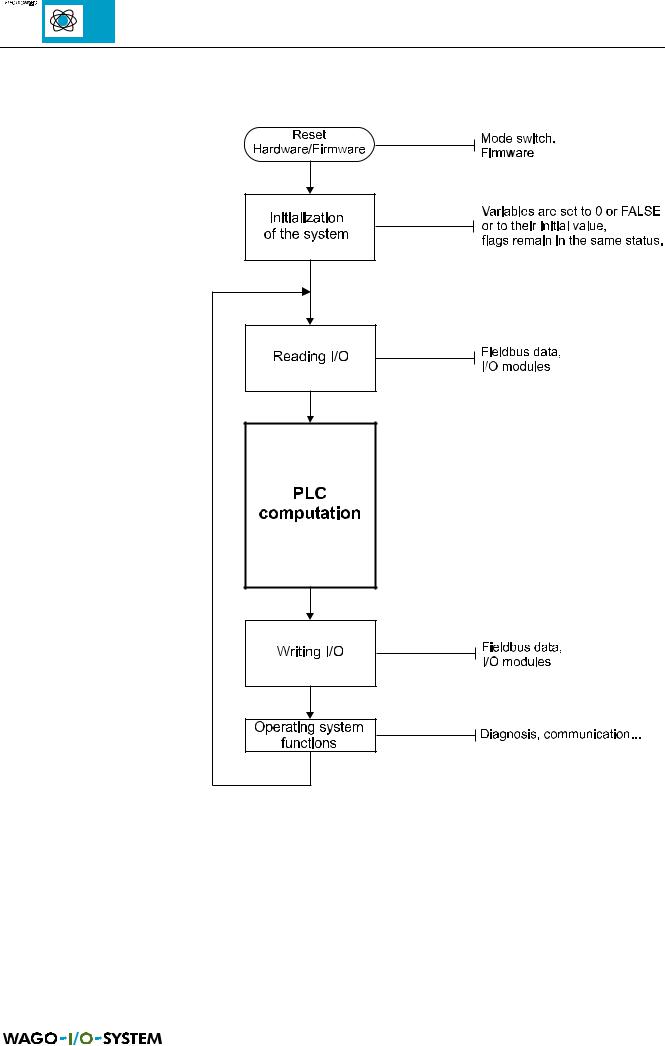
5.2.6 Controller operating system
Fig. 5.13: Operating system, controller
52 |
MODBUS / Configuration |
15.12.99

5.3 Common coupler/controller functions
5.3.1 Implemented MODBUS functions
The following table shows the functions which support both the MODBUS coupler as well as the MODBUS controller:
Function |
Function |
Description |
|
code |
|
|
|
|
|
|
|
0x01 |
Read Coil Status |
Read input bits and output bits as an octet string. |
Functions are |
|
|
|
|
0x02 |
Read Input Status |
Read input bit as an octet string. |
identical |
|
|||
|
|
|
|
0x03 |
Read Holding Registers |
Read number of input words. |
Functions are |
|
|
|
|
0x04 |
Read Input Registers |
Read number of input words. |
identical |
|
|||
|
|
|
|
0x05 |
Force Single Coil |
Write output bit. |
|
|
|
|
|
0x06 |
Preset Single Register |
Writes a value in an output word. |
|
|
|
|
|
0x0B |
Fetch Comm Event Ctr |
Read status word and event counter. |
|
|
|
|
|
0x0F |
Force Multiple Coils |
Writes a number of output bits. |
|
|
|
|
|
0x10 |
Preset Multiple Regs |
Writes a number of output words. |
|
|
|
|
|
Table 5.29: Implemented functions
MODBUS / Configuration |
53 |
15.12.99
5.3.1.1 Use of the MODBUS functions
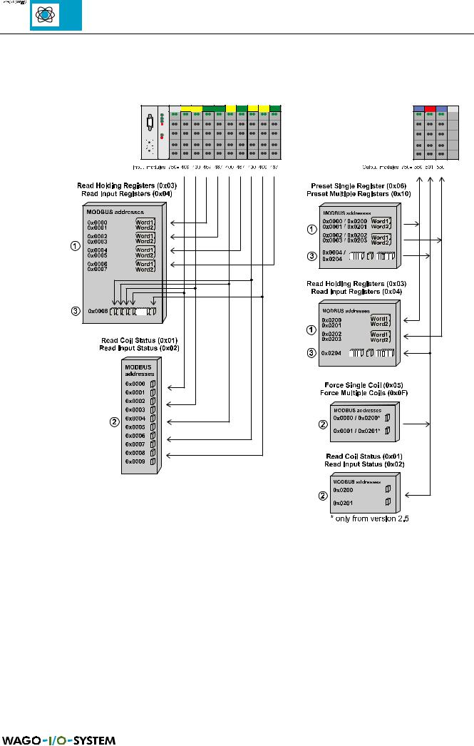
The graphical review shows the MODBUS functions which have access to process illustration data.
Fig. 5.14: Review of MODBUS functions, e.g. with coupler
It is to be recommended to access the analog signals with register functions and binary signals with coil functions . If access is also required to reading and writing binary signals with register functions , the addresses are displayed as soon as a further analog modules are fitted.
54 |
MODBUS / Configuration |
15.12.99

5.3.1.2 Read Coil Status (function code 0x01):
This function reads the status of the input and output bits (coils) in slave, whereby broadcast is not supported. With coupler/controller the number of I/O points is limited to 256.
Inquiry:
яюэьыъщэш The Inquiry determines the starting address and the number of bits to be read.
The first point is addressed with 0. With Modicon the addressing starts with 1 (0x01).
The following table shows an example for an inquiry, with which the bits 0 to 7 of the slaves 11 are to be read:
Field name |
Example |
RTU |
ASCII |
|
Start of frame |
- |
t1-t2-t3 |
”:” |
0x3a |
Slave address |
0x0B |
0x0B |
”0B” |
0x30, 0x42 |
Function code |
0x01 |
0x01 |
”01” |
0x30, 0x31 |
Starting address high |
0x00 |
0x00 |
”00” |
0x30, 0x30 |
Starting address low |
0x00 |
0x00 |
”00” |
0x30, 0x30 |
Number of points high |
0x00 |
0x00 |
”00” |
0x30, 0x30 |
Number of points low |
0x08 |
0x08 |
”08” |
0x30, 0x38 |
Error Check (LRC / CRC) |
- |
0x3D |
”EC” |
0x45, 0x43 |
|
|
0x66 |
|
|
End of frame |
|
t1-t2-t3 |
- |
0xD, 0xA |
Table 5.30: Inquiry example, Read Coil Status |
|
|
|
|
Reply:
The current values of the interrogated bits are packed in the data field. A 1 corresponds to the ON status and a 0 to the OFF status. The lowest value bit of the first data byte contains the first bit of the inquiry. The others follow in an ascending order. If the number of inputs are not a multiple of 8, the remaining bits of the last data byte are filled with zeroes. If the number of bits interrogated exceed the number of inputs or outputs present in the node, the remaining input bits are set to zero and the outputs contain the last valid value.
Field name |
Example |
RTU |
ASCII |
|
Start of frame |
- |
t1-t2-t3 |
”:” |
0x3A |
Slave address |
0x0B |
0x0B |
”0B” |
0x30, 0x42 |
Function code |
0x01 |
0x01 |
”01” |
0x30, 0x31 |
Byte Count |
0x01 |
0x01 |
”01” |
0x30, 0x31 |
Data (point 8...0) |
0x12 |
0x12 |
”12” |
0x31, 0x32 |
Error Check (LRC / CRC) |
- |
0xD2 |
”E1” |
0x45, 0x31 |
|
|
0x5D |
|
|
End of frame |
- |
t1-t2-t3 |
- |
0xD, 0xA |
Table 5.31: Reply example, Read Coil Status
MODBUS / Configuration |
55 |
15.12.99