I/O modules • 203
Analog Inputs 750-472, -474
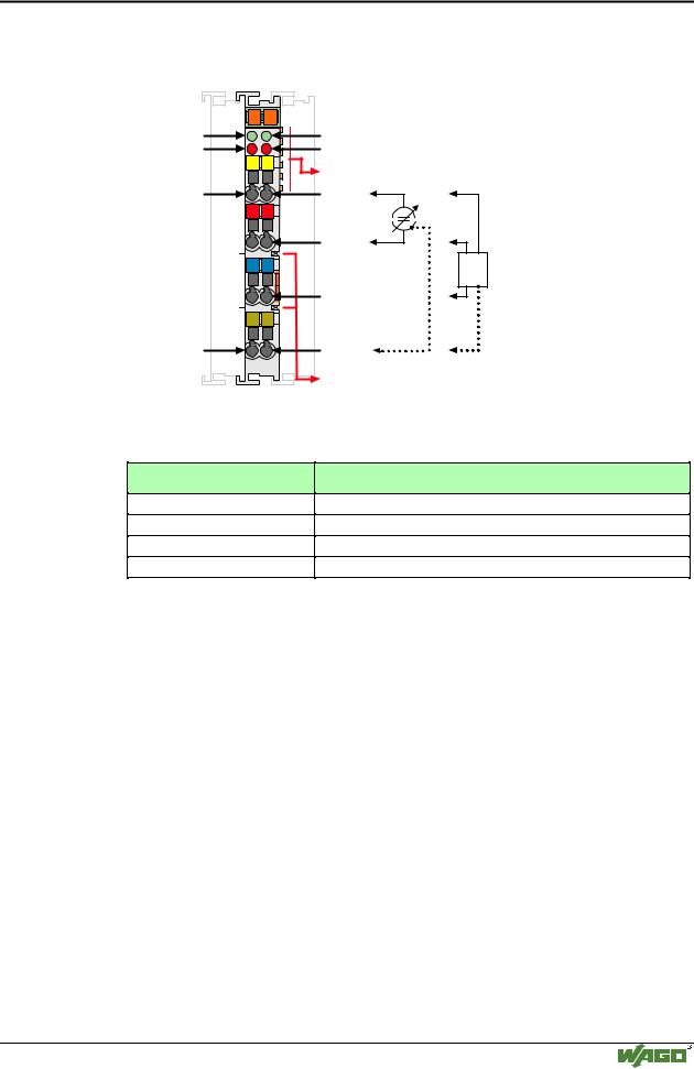
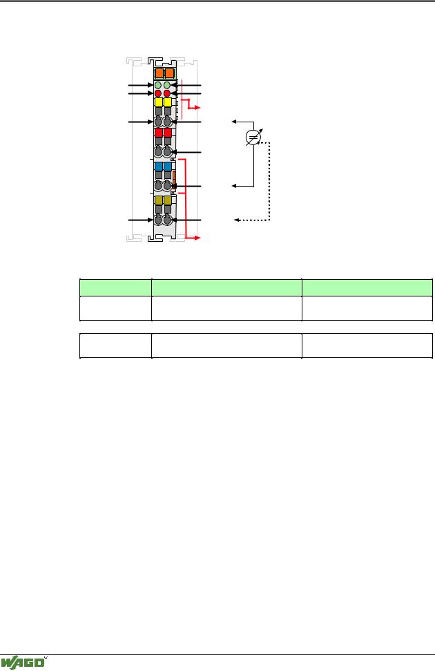
4.4.1.1.92 Channel Analog Inputs
(0-20mA / 4-20mA single-ended) 750-472, -474
Function AI 1
Error AI 1
AI 1
Shield (screen)
13 |
14 |
A |
|
|
C |
B |
|
|
D |
E1 |
E2 |
+ |
+ |
0V |
0V |
S |
S |
750-472 |
Function AI 2
Error AI 2
Data contacts
AI 2
24V
0V
Shield (screen)
Power jumper contacts
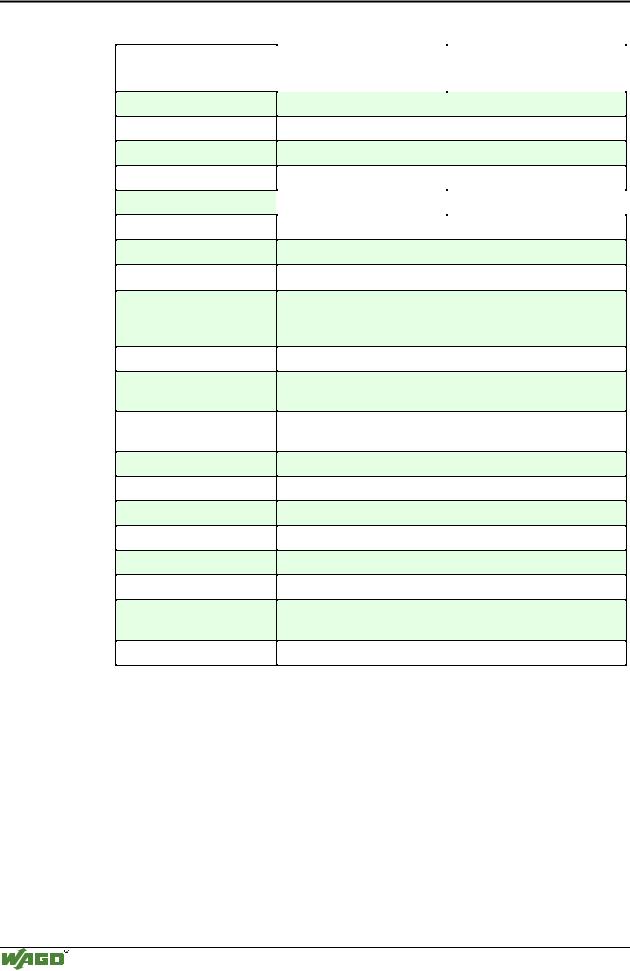
I/O modules and variations
Item-No.:
750-472
750-472/000-200
750-474
750-474/000-200
Name:
2AI 0-20mA 16 Bit s.e.
2AI 0-20mA 16 Bit s.e. S5-463
2AI 4-20mA 16 Bit s.e.
2AI 4-20mA 16 Bit s.e. S5-460 /465
Technical description
This description is only intended for hardware and software version X X X X 0 2 0 2- - -- 0 5 0 3.
The serial number can be found on the right side of the module.
The input channels are single ended and they have a common ground potential.
The inputs are connected to +I. Via 24 V / 0 V power can be provided directly to the sensor from the module. Power connections are made automatically from module to module through the PJC when snapped onto the DIN rail.
The shield is connected to "S". The connection is made automatically when snapped onto the DIN rail.
The input module can operate with all buscouplers of the
WAGO-I/O-SYSTEM (except for the economy type).
Modular I/O System
ETHERNET TCP/IP