Материал: m012900e
I/O modules • 189
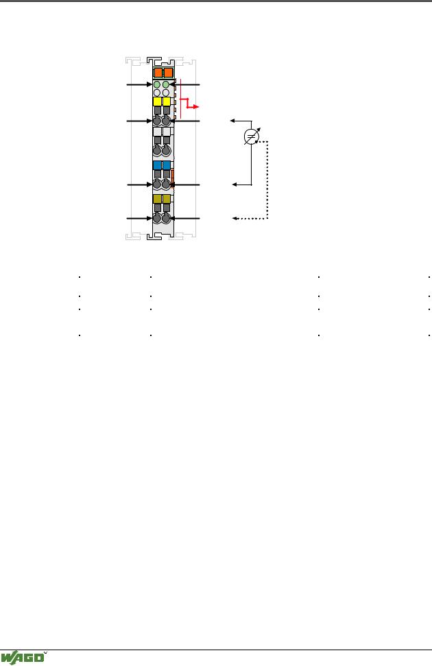
Analog Inputs 750-465, -466, (-486)
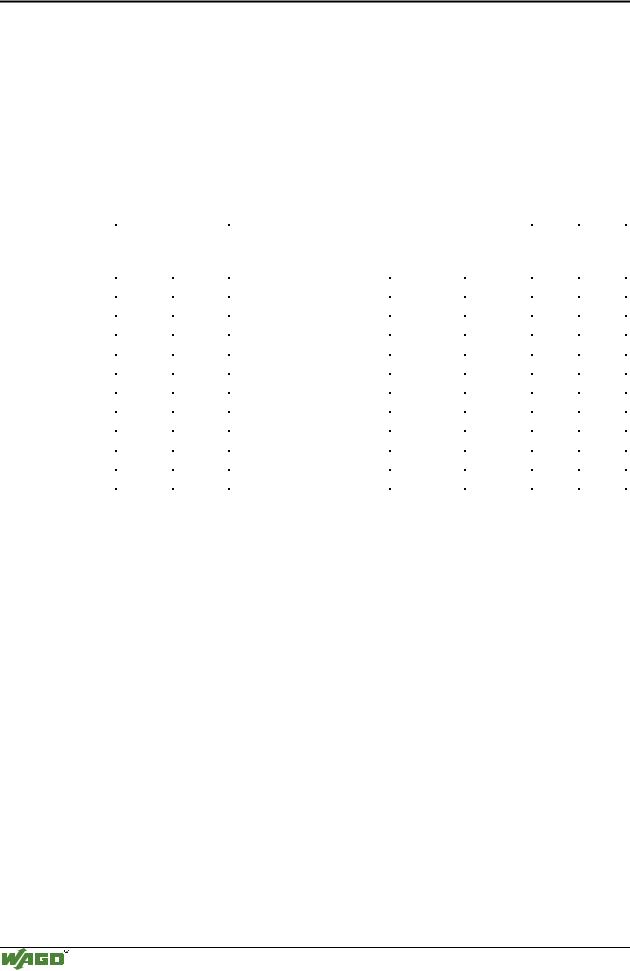
750-465/000-200 (formerly 485)
Input |
|
|
|
|
|
|
Value |
|
|
|
|
|
|
Status |
LED |
|||
current |
|
|
Binary |
|
|
X E O *) |
|
Hex. |
|
|
Dec. |
|
|
|
Error |
|||
0-20 mA |
|
|
|
|
|
|
|
|
|
|
|
|
|
|
|
E (1,2) |
||
>20.5 |
|
0101 0000 0000 0 |
|
|
0 0 1 |
|
0x5001 |
20481 |
0x42 |
on |
||||||||
|
|
|
|
|
|
|
|
|
|
|
|
|
|
|
|
|
||
|
|
|
|
|
|
|
|
|
|
|
|
|
|
|
|
|
||
20 |
|
0101 0000 0000 0 |
|
|
0 0 0 |
|
0x5000 |
20480 |
0x00 |
off |
||||||||
|
|
|
|
|
|
|
|
|
|
|
|
|
|
|
|
|
||
10 |
|
0011 0000 0000 0 |
|
|
0 0 0 |
|
0x3000 |
12288 |
0x00 |
off |
||||||||
|
|
|
|
|
|
|
|
|
|
|
|
|
|
|
|
|
||
5 |
|
0010 0000 0000 0 |
|
|
0 0 0 |
|
0x2000 |
8192 |
0x00 |
off |
||||||||
|
|
|
|
|
|
|
|
|
|
|
|
|
|
|
|
|
||
2.5 |
|
0001 1000 0000 0 |
|
|
0 0 0 |
|
0x1800 |
6144 |
0x00 |
off |
||||||||
|
|
|
|
|
|
|
|
|
|
|
|
|
|
|
|
|
||
|
|
|
|
|
|
|
|
|
|
|
|
|
|
|
|
|
||
0.312 |
|
0001 0001 0000 0 |
|
|
0 0 0 |
|
0x1100 |
4608 |
0x00 |
off |
||||||||
|
|
|
|
|
|
|
|
|
|
|
|
|
|
|
|
|
||
0.019 |
|
0001 0000 0001 0 |
|
|
0 0 0 |
|
0x1010 |
4112 |
0x00 |
off |
||||||||
|
|
|
|
|
|
|
|
|
|
|
|
|
|
|
|
|
||
0.0097 |
|
0001 0000 0000 1 |
|
|
0 0 0 |
|
0x1008 |
4104 |
0x00 |
off |
||||||||
|
|
|
|
|
|
|
|
|
|
|
|
|
|
|
|
|
||
0 |
|
0001 0000 0000 0 |
|
|
0 0 0 |
|
0x1000 |
4096 |
0x00 |
off |
||||||||
|
|
|
|
|
|
|
|
|
|
|
|
|
|
|
|
|||
|
|
|
|
|
|
|
|
|
|
|
|
|
|
|
|
|||
*) X : without meaning, E : short circuit or open circuit, O : overflow |
|
|||||||||||||||||
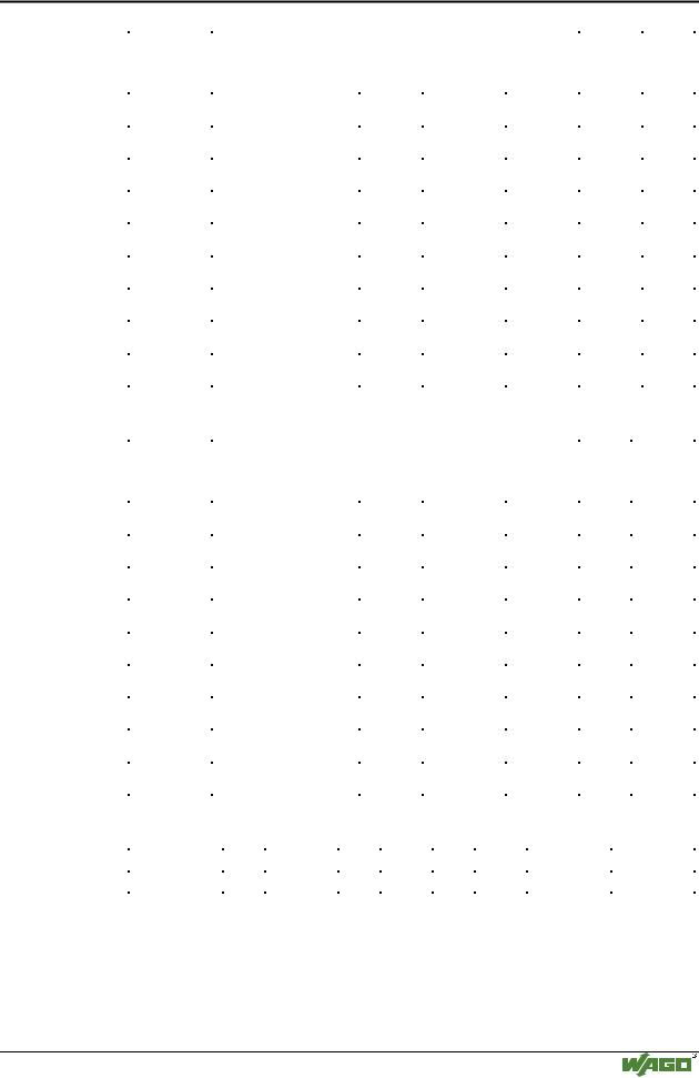
750-466/000-200 (formerly 750-486) |
|
|
|
|
|
|
|
|
|
|
||||||||
Input- |
|
|
|
|
|
|
Value |
|
|
|
|
|
|
Status |
|
LED |
||
current |
|
|
Binary |
|
|
X E O *) |
|
Hex. |
|
|
Dec. |
|
|
|
Error |
|||
0-20 mA |
|
|
|
|
|
|
|
|
|
|
|
|
|
|
|
E (1,2) |
||
|
|
|
|
|
|
|
|
|
|
|
|
|
|
|
|
|
||
>20.5 |
|
0101 0000 0000 0000 |
|
0 0 1 |
|
0x5001 |
20481 |
0x42 |
|
on |
||||||||
|
|
|
|
|
|
|
|
|
|
|
|
|
|
|
|
|
||
20 |
|
0101 0000 0000 0000 |
|
0 0 0 |
|
0x5000 |
20480 |
0x00 |
|
off |
||||||||
|
|
|
|
|
|
|
|
|
|
|
|
|
|
|
|
|
||
12 |
|
0011 0000 0000 0000 |
|
0 0 0 |
|
0x3000 |
12288 |
0x00 |
|
off |
||||||||
|
|
|
|
|
|
|
|
|
|
|
|
|
|
|
|
|
||
8 |
|
0010 0000 0000 0000 |
|
0 0 0 |
|
0x2000 |
8192 |
0x00 |
|
off |
||||||||
|
|
|
|
|
|
|
|
|
|
|
|
|
|
|
|
|
||
|
|
|
|
|
|
|
|
|
|
|
|
|
|
|
|
|
||
6 |
|
0001 1000 0000 0000 |
|
0 0 0 |
|
0x1800 |
6144 |
0x00 |
|
off |
||||||||
|
|
|
|
|
|
|
|
|
|
|
|
|
|
|
|
|
||
4.25 |
|
0001 0001 0000 0000 |
|
0 0 0 |
|
0x1100 |
4608 |
0x00 |
|
off |
||||||||
|
|
|
|
|
|
|
|
|
|
|
|
|
|
|
|
|
||
4.016 |
|
0001 0000 0001 0000 |
|
0 0 0 |
|
0x1010 |
4112 |
0x00 |
|
off |
||||||||
|
|
|
|
|
|
|
|
|
|
|
|
|
|
|
|
|
||
4 |
|
0001 0000 0000 0000 |
|
0 0 0 |
|
0x1000 |
4096 |
0x00 |
|
off |
||||||||
|
|
|
|
|
|
|
|
|
|
|
|
|
|
|
|
|
||
|
|
|
|
|
|
|
|
|
|
|
|
|
|
|
|
|
||
<3.5 |
|
0001 0000 0000 0000 |
|
0 1 1 |
|
0x1003 |
4099 |
0x41 |
|
on |
||||||||
|
|
|
|
|
|
|
|
|
|
|
|
|
|
|
|
|||
*) X : without meaning, E : short circuit or open circuit, O : overflow |
|
|||||||||||||||||
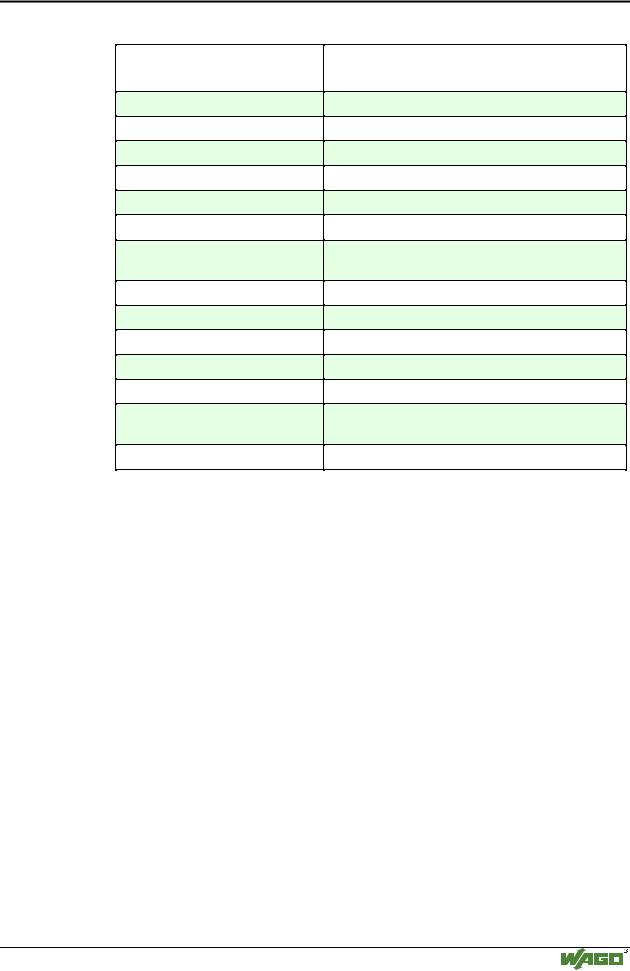
Status byte |
|
|
|
|
|
|
|
|
|
|
|
|
|
|
|
|
|
|
Bit |
7 |
|
6 |
5 |
|
|
4 |
|
3 |
|
2 |
|
1 |
|
0 |
|
|
|
Meaning |
0 |
|
ERROR |
res. |
|
res. |
|
res. |
|
res. |
|
Overrange |
Underrange |
|||||
ERROR |
Error at the input channel. |
|
|
|
|
|
|
|
|
|
|
|||||||
Overrange |
The input signal is over the admissible measuring range, if necessary it exists a |
|||||||||||||||||
|
|
short-circuit. |
|
|
|
|
|
|
|
|
|
|
|
|
|
|
||
Underrange |
The input signal is under the admissible measuring range, if necessary it exists |
|||||||||||||||||
|
|
an open circuit (only for module 750-466). |
|
|
|
|
|
|
||||||||||
Res. |
Reserved, not currently used |
|
|
|
|
|
|
|
|
|
|
|||||||
Modular I/O System
ETHERNET TCP/IP