Материал: яаыф

Energies 2018, 11, 2463 |
6 of 20 |
3. Efficiency
Efficiency improvement achieved using DC distribution systems compared to AC distribution systems can be attributed to various reasons. The main reason for higher efficiency of DC systems is it requires lower number of power conversion stages. In current architectures, the majority of residential and commercial loads comprise of electronic loads that require DC power. To supply these loads using a conventional AC distribution system, a power electronic converter is required to first convert AC to DC. This power conversion from AC to DC results in additional power losses, usually about 4–15% of the input power; assuming the converters are 85–96% efficient. Therefore, the total system losses become relatively high as the number of power converters increase. Applications using variable speed drives, a washing machine or heating, ventilation, and air conditioning (HVAC) systems for example, require a rectifier for AC to DC conversion and then another converter to generate variable AC. Having a DC system eliminates the use of the rectifier stage thereby improving the system efficiency.
The power conversion road map for AC and DC power systems given in Table 2 [23] shows that DC systems have fewer conversion stages compared to AC systems for DC loads, AC loads, and AC loads with AC converters (ACwC Load).
Table 2. Power conversion roadmap for AC and DC power systems [23].
System |
Source |
DC Load |
AC Load |
ACwC Load |
|
AC |
DC |
DC–AC–DC |
DC–AC |
DC–AC–DC–AC |
|
|
|
|
|
||
AC |
AC–DC |
- |
AC–DC–AC |
||
|
|||||
|
|
|
|
|
|
DC |
DC |
- |
DC–AC |
DC–AC |
|
|
|
|
|
||
AC |
AC–DC |
AC–DC–AC |
AC–DC–AC |
||
|
|||||
|
|
|
|
|
From another point of view, the absence of reactive power and skin effect are other reasons for improved efficiency in a DC distribution system compared to an AC distribution system. Since there is no reactive power in a DC system, the apparent and active powers are equal, which results in reduced losses in the system. In an AC system, skin effect increases the effective resistance of the wires and therefore results in higher distribution losses. Since such an effect is absent in a DC system, it has better efficiency than an AC system.
Various studies have been performed to validate the efficiency improvement in a DC distribution system. Lawrence Berkley national laboratory (LBNL) started investigating the DC distribution efficiency in data centers in 2004. The results obtained in their study stated that DC distribution consumed 28% less power compared to a typical AC distribution in data centers [20,24,25]. In reference [26], 220 Vac distribution was compared to 400 Vdc for power distribution in buildings. It was observed that in switching from AC to DC, an efficiency gain of 17.7%, 9.49%, and 18.9% was achieved in office, residential, and school buildings, respectively. The investigation carried out in [25] concluded that at 50% load, 380 Vdc system was the most efficient among the systems considered for study. The results of this study are shown in Table 3. The author of reference [27] explains that when a distribution system integrated with DC sources (e.g., fuel cells, solar panels, etc.) was considered, a DC distribution system was more efficient than an AC system.
Table 3. Efficiency comparison of five distribution systems at 50% load [25].
System |
Uninterruptible Power Supply |
Distribution |
IT Power Supply |
Overall Efficiency |
|
(UPS) |
|||||
|
|
|
|
||
|
|
|
|
|
|
480 to 208 Vac |
96.20% |
96.52% |
90.00% |
83.56% |
|
400/230 Vac |
96.20% |
99.50% |
90.25% |
86.39% |
|
48 Vdc |
92.86% |
99.50% |
91.54% |
84.58% |
|
380 Vdc |
96.00% |
99.50% |
91.75% |
87.64% |
|
Hybrid 575 Vdc |
95.32% |
92.54% |
91.54% |
80.74% |
|
|
|
|
|
|
Energies 2018, 11, 2463 |
7 of 20 |
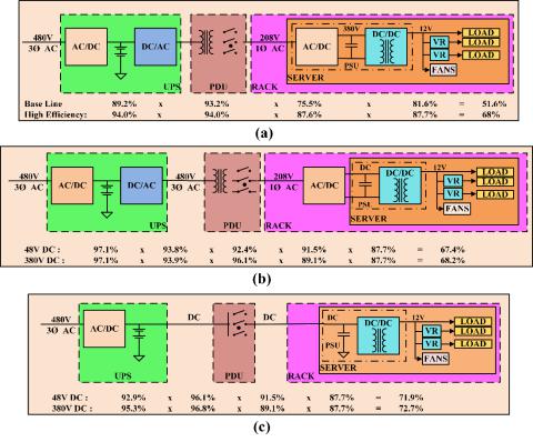
Low voltage DC systems designed for applications such as telecom and datacenters operate at 48 Vdc. At least three conversion stages from the AC input to the load are required to achieve this voltage level, which reduces the system efficiency. In references [28–36], different voltage levels have been proposed for a DC bus based on efficiency, cost, and reliability considerations. In references [3,4], three different power architectures, namely conventional AC architecture, rack-level DC architecture, and facility-level DC architecture, have been described that are commonly utilized in data and telecom centers. Conventional AC system architecture for data center applications, shown in Figure 3a, has several conversion stages that include the double conversion stage of the uninterruptible power supply (UPS). The AC input voltage is first converted to DC, where the energy storage system is connected, and then converted back to AC. In the next stage the voltage is stepped down to 208 Vac using a transformer in the power distribution unit (PDU). This AC voltage is once again converted to a DC voltage in the range of 380–400 Vdc using an AC–DC converter in the power supply unit (PSU). Isolated DC–DC converters are used to step down the voltage to levels suitable for distribution to the loads. For this configuration the overall system efficiency when operated at high load conditions is typically around 50%.
In the rack-level DC configuration presented in Figure 3b, the AC–DC converter is shifted from the PSU of the server to the rack, thus reducing the server cooling requirements. The server volume is also reduced and the whole consolidated rack has higher power density and improved light load efficiency. Compared to the conventional AC architecture, an improvement in the overall system efficiency is not expected since the number of conversion stages are the same.
In the facility-level DC architecture shown in Figure 3c, the DC–AC conversion stage in the UPS, the AC–DC conversion stage in the PSU of the server, and the transformer in the PDU are removed. Therefore, the number of conversion stages are reduced and the power delivery efficiency is
significantly increased. |
8 of 21 |
Energies 2018, 11, x FOR PEER REVIEW |
Figure 3. Power architectures in telecom and data centers: (a) conventional AC architecture;
Figure 3. Power architectures in telecom and data centers: (a) conventional AC architecture; (b) rack-
(b) rack-level DC architecture; (c) facility-level DC architecture [4]. level DC architecture; (c) facility-level DC architecture [4].
In reference [36], a 380 Vdc modified power delivery architecture was proposed for server applications because it is more efficient than the conventional 48 Vdc system. In the modified power delivery architecture, the improvement in efficiency is obtained by reducing the number of power conversion stages and placing isolated DC–DC converters close to the load. Based on the abovementioned references and their claims, one can reach the conclusion that not only is a DC
Energies 2018, 11, 2463 |
8 of 20 |
In reference [36], a 380 Vdc modified power delivery architecture was proposed for server applications because it is more efficient than the conventional 48 Vdc system. In the modified power delivery architecture, the improvement in efficiency is obtained by reducing the number of power conversion stages and placing isolated DC–DC converters close to the load. Based on the abovementioned references and their claims, one can reach the conclusion that not only is a DC distribution system more efficient than a conventional AC system, but a higher voltage DC system also offers higher efficiency.
4. Safety and Protection
Two of the main concerns associated with DC distribution are the risk of electric shock and protecting equipment from damage that can also result in electric fires. The main reason behind this concern is that it is challenging to break a DC current compared to an AC current. Switchgear including circuit breakers, fuses, etc., and proper grounding methods are required to make the DC system safer. Comprehensive research has been conducted and papers have been published on improving the safety in DC distribution systems [37–40]; different papers have studied protection against electric shock related to DC generating devices such as photovoltaic generators from the perspective of personal safety [41,42]. Moreover, higher DC voltage levels would result in leakage currents in the system that can cause corrosion of the underground equipment, transformer saturation, and faulty operation of protective equipment [43].
4.1. Personal Protection
In order to evaluate personal protection and safety requirements of DC and AC systems, it is important to understand the effects of DC and AC currents on human body. The effect of an electric shock depends on the current magnitude, the duration of current, the current path, and the type of voltage (AC or DC). Among all the possible effects of electric shock, ventricular fibrillation is the
Energies 2018, 11, x FOR PEER REVIEW 9 of 21
most dangerous. Hence, in order to prevent any casualties proper protection needs to be provided.
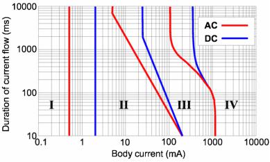
The authors of [37,39], provide a characteristic curve of body current (AC and DC) vs. the duration of authors of [37,39], provide a characteristic curve of body current (AC and DC) vs. the duration of
current flow, which is shown in Figure 4. current flow, which is shown in Figure 4.
FigureFigure4. Characteristic4. curvecurveofofbodycurrentre t vs. durationofoflow,flow,IEC/TR6047960479-5 [37]-5.[37].
The graphThe graphis divideds dividedintointofourfourregionsbasedon the effectsononthethehumanhumanbody:body:
I.No effect
I. No effect
II.A little pain but no dangerous effects
II.A little pain but no dangerous effects
III. Muscular contraction and respiratory compromise, which are reversible
III.Muscular contraction and respiratory compromise, which are reversible
IV. Critical effects such as ventricular fibrillation
IV. Critical effects such as ventricular fibrillation
It can be observed from the figure that the magnitude of safe operating current limit for DC is higher compared to AC, thus making DC safer to operate than AC.
4.2. Equipment Protection
Protective devices such as circuit breakers and fuses are similar for both the AC and DC systems. However, in the case of DC systems, they have to tolerate more stress while breaking the current due to the persistent nature of the arc. For residential applications and DC buildings, circuit breakers are
Energies 2018, 11, 2463 |
9 of 20 |
It can be observed from the figure that the magnitude of safe operating current limit for DC is higher compared to AC, thus making DC safer to operate than AC.
4.2. Equipment Protection
Protective devices such as circuit breakers and fuses are similar for both the AC and DC systems. However, in the case of DC systems, they have to tolerate more stress while breaking the current due to the persistent nature of the arc. For residential applications and DC buildings, circuit breakers are commonly used instead of fuses as they can be reset when the fault is cleared. As the voltage and current ratings of the circuit breakers are lower for a DC system compared to an AC system, same components can be used for protection on both the AC and DC sides of a system. Furthermore, in the event of a short circuit, individual converters are usually equipped with short circuit protection and can easily detect a fault by observing the DC bus voltage. In such cases, when the DC bus voltage falls below a certain threshold, the controller can identify a short circuit and shut down the
system. However, DC fault currents in some compact devices pose many challenges that demand
Energies 2018, 11, x FOR PEER REVIEW 10 of 21 advanced electrical protection requirements, therefore making the selection of suitable DC circuit
breaker technology much more challenging [44].
equipped with mechanical locks to ensure human safety. The Nippon Telegraph and Telephone
Many advantages of DC distribution systems are currently driving the market growth for DC
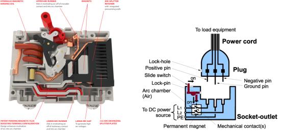
(NTT) Corporation and Fujitsu Component Limited have developed a 400 Vdc, 10 A plug and socket,
technologies. Since equipment protection has been a major concern, many companies have been as shown in Figure 5b, which can be used for DC distribution system [38]. When a DC current is
researching DC protection devices. Currently, major companies have started providing products used interrupted, the resulting arc can damage the equipment. To prevent this, the plug should not be
in DC distribution that follow existing standards for safety. Companies like ASEA Brown Boveri (ABB), removed from the socket when the power supply is on. However, there can be instances during
Carling Technologies, Schneider, Nader, Siemens, etc., provide DC circuit breakers and fuses to be used emergencies or when the plug is accidentally removed from the socket while the power is still on.
for safety and protection purposes in DC distribution systems. Figure 5a shows the design features of
During those cases, the plug and socket should be capable of taking care of the arc extinction and
CX-series circuit breakers of Carling Technologies that is ideal for 380 Vdc applications [45]. It uses a shock prevention tasks.
special arc-quenching method, enabling it to break high DC currents and handle high DC voltages.
(a) |
(b) |
Figure 55.. (a()a)DesignfeaturesofofCarlingCarlingTechTechDCDCcircircuitbreakerbreaker(© (©of Carlingof CarlingTech)Tech)[45];45(b];) (configurationb) configurationof DCof DCplugplugandandsocketsocketoutletletsystemsystem(©(©of ofNTTNTTFacilities)[38]38. ].
4.3. GroundingDC distributionMethodssystems for commercial buildings and data centers require a distinctive plug
and socket that should provide arc extinction as well as prevent electric shocks. These plugs are
Grounding is a mandatory requirement in distribution systems as it provides personal safety also equipped with mechanical locks to ensure human safety. The Nippon Telegraph and Telephone and decreases the risk of fire hazards. Also, it reduces equipment damage, service interruptions
(NTT) Corporation and Fujitsu Component Limited have developed a 400 Vdc, 10 A plug and socket, during short circuit and earth faults. Other advantages of grounding include reduced radiation and as shown in Figure 5b, which can be used for DC distribution system [38]. When a DC current is conduction of electromagnetic emissions, providing tolerance to electrostatic discharge and lightning interrupted, the resulting arc can damage the equipment. To prevent this, the plug should not be interference. Different grounding methods discussed in [37,39,40] are as follows:
removed from the socket when the power supply is on. However, there can be instances during
4.3.1. Direct Grounding Method
This type of grounding involves connecting one of the lines directly to the ground. There are three ways in which direct grounding can be implemented. They are listed below:
1.Positive line grounding: In this system, the positive line is connected to ground as shown in
Energies 2018, 11, 2463 |
10 of 20 |
emergencies or when the plug is accidentally removed from the socket while the power is still on. During those cases, the plug and socket should be capable of taking care of the arc extinction and shock prevention tasks.
4.3. Grounding Methods
Grounding is a mandatory requirement in distribution systems as it provides personal safety and decreases the risk of fire hazards. Also, it reduces equipment damage, service interruptions during short circuit and earth faults. Other advantages of grounding include reduced radiation and conduction of electromagnetic emissions, providing tolerance to electrostatic discharge and lightning interference. Different grounding methods discussed in [37,39,40] are as follows:
4.3.1. Direct Grounding Method
This type of grounding involves connecting one of the lines directly to the ground. There are three ways in which direct grounding can be implemented. They are listed below:
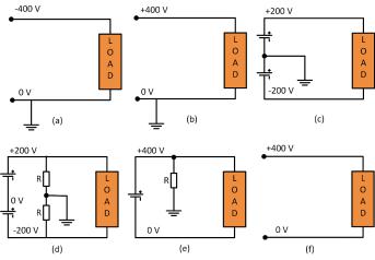
1.Positive line grounding: In this system, the positive line is connected to ground as shown in Figure 6a. This system provides easy detection and breaking of current during a short circuit or earth fault. Monopole breaking is used to break the current. During a fault, the direction of the current through the human heart is upward and the heart-current factor F [39] is twice that of the direct negative grounding system. As a result, it seems like twice the current is flowing through the human body. The current one receives during an electric shock in this type of grounding is the largest among all the grounding systems as the circuit impedance is very low. However, as the fault current is large, it can be interrupted with better accuracy.
2.Negative line grounding: In this type of grounding the negative line is connected to the ground as shown in Figure 6b. The properties of this grounding method are similar to positive line grounding. The current one receives in this type of grounding is usually high, but not as high as positive line grounding.
3.Mid-point line grounding: In this type of grounding, the voltage to grounding is half of that compared to one end grounding as shown in Figure 6c. It is easy to detect and break currents during short circuit and ground faults. The current is usually large when short circuit or earth faults occur on the negative line. When breaking fault current, it is necessary to break both the positive and negative lines at the same time. Usually, rectifiers and batteries implement this type
of grounding and hence they need to deal with higher initial costs.
Energies 2018, 11, x FOR PEER REVIEW |
12 of 21 |
Figure 6. Grounding methods: (apositive) itive line; (b) negative line; (c) mid-poiline;t; (d) midmid-po nt high resistance; (e)
Figure 6. Grounding methods: (a) line; (b) negative (c) -point; (d) mid-point high
one-end high resistance; (f) floating system.
resistance; (e) one-end high resistance; (f) floating system.
5. Reliability
The reliability of both AC and DC systems depends on their system architecture and the level of redundancies. Especially, in DC systems, increasing the system voltage level adversely affects the electrical stresses experienced by the components (switches, breakers, etc.), thereby reducing the reliability of the system. Switching devices like power MOSFETs, IGBTs, diodes, etc. should always be operated within their safe operating area and, hence, are selected considering enough safety margins to take care of the voltage and current transients.
It has been observed that an increase in bus voltages reduces the life of capacitors [46]. The lifetime of electrolytic capacitors is given by