Материал: яаыф
 ENERGIES
Review
An Overview of Direct Current Distribution System
Architectures & Benefits
Venkata Anand Prabhala 1,*, Bhanu Prashant Baddipadiga 1, Poria Fajri 2 and Mehdi Ferdowsi 1
1Electrical and Computer Engineering Department, Missouri University of Science and Technology, Rolla,
MO 65401, USA; bbt68@mst.edu (B.P.B.); ferdowsi@mst.edu (M.F.)
2Electrical and Biomedical Engineering Department, University of Nevada, Reno, NV 89557, USA; pfajri@unr.edu
* Correspondence: vkpzvf@mst.edu; Tel.: +1-424-397-7779
Received: 12 August 2018; Accepted: 11 September 2018; Published: 17 September 2018 |
|
Abstract: This paper examines existing and future direct current (DC) distribution systems with a wide range of applications in data centers, telecommunication systems, commercial buildings, residential homes, electric vehicles, spacecraft, and aircrafts. DC distribution systems have many advantages and disadvantages over their alternating current (AC) counterparts. There are a few surviving examples of DC distribution systems; among them are the telecommunication systems and data centers that use the low-voltage 48 Vdc systems. However, recently, there has been a move towards higher DC bus voltages. In this paper, a comparative study of different DC distribution architectures and bus structures is presented and voltage level selection is discussed for maximizing system efficiency and reliability, reducing system costs, and increasing the flexibility of the system for future expansion. Furthermore, DC distribution systems are investigated from a safety standpoint and the current global market for these distribution systems is also discussed.
Keywords: DC distribution system; bus structure; power architectures; safety; protection; reliability; cost; voltage level
1. Introduction
DC power distribution systems were first proposed for lighting purposes and were patented by Edison in 1883 [1]. Due to limited advancements in DC technology, DC distribution systems were deemed inefficient and hence unsuitable for transmission of power over long distances. In 1886, Sprague proposed AC distribution systems [2]. With the invention of transformers and induction machines, AC distribution systems could transmit power efficiently over long distances. As a result, they became popular and were universally adopted for electric power distribution. The advent of the semiconductor industry in the 1960s led to the introduction of power electronic converters (PECs) that were capable of improving the performance of DC distribution systems. With everyday advancements in semiconductor technology, PECs are becoming more efficient, reliable, cheaper, and smaller in size. With the help of PECs, DC distribution systems are now becoming more beneficial than AC distribution systems in terms of efficiency, reliability, cost, size, etc. [3,4]. In references [5–13], the authors propose new topologies of PECs with high efficiencies and power densities that can be used to improve the overall efficiency of a DC distribution system.
A DC distribution system has many advantages over an AC distribution system. It offers higher efficiency and reliability at an improved power quality. It has reduced installation costs as it requires fewer power conversion stages, less copper, and smaller floor space. DC distribution enables simpler integration of renewable energy sources and energy storage systems. Since the power is distributed in DC, there is no reactive power or skin effect in the system. Unlike the AC
Energies 2018, 11, 2463; doi:10.3390/en11092463 |
www.mdpi.com/journal/energies |
Energies 2018, 11, 2463 |
2 of 20 |
distribution system, a DC distribution system facilitates plug and play features as it does not require any synchronization. Telecommunication systems and data centers are among the few surviving examples of DC distribution systems. They are low voltage (48 Vdc) power systems that have characteristics similar to a conventional DC distribution system. The requirement of DC power for major consumer electronic loads and recent developments in renewable energy technology as well as increased penetration of distributed energy resources have prompted renewed interest in DC distribution systems among researchers and industry players.
Ideally, a power delivery architecture should maximize system efficiency and provide power at a low cost. It should also be able to reliably supply power to critical and sensitive loads such as data centers, as these applications require uninterrupted power supply. Moreover, there should be room for further expansion as and when necessary. In this paper, different DC distribution system architectures are discussed and a comparative study is presented. The authors of references [3,4], and references [14–22] show different power delivery architectures used for both AC and DC systems for different voltage levels. The optimum DC bus voltage level selection is done to maximize system efficiency, reliability, and flexibility of the system for future expansion while reducing system costs. Until the last decade most telecommunication and data centers were operating at 48 Vdc, as it is within the safe extra low voltage limits of the European Telecom standards EN41003 and UL 1950 to avoid hazards [20,21]. Recently, there has been a trend towards moving to higher DC bus voltages to reduce system costs and losses. However, there are challenges involved with higher DC bus voltages like safety and protection that can lead to fire hazards. Furthermore, the reliability of the system is also affected, as there is an increased risk of component failure involved with increased voltage and current stresses. This paper discusses the DC bus voltage level selection based on different safety standards and investigates the different aspects of DC systems in terms of system reliability and efficiency, ease of integration of renewable energy and energy storage systems, and availability of protection equipment and components.
In this paper, Section 2 gives a brief overview of different power distribution architectures and DC bus structures for DC distribution systems at different voltage levels. Section 3 discusses the efficiency improvement in DC systems. The safety, grounding, and protection aspects of DC systems are discussed in Section 4. Sections 5 and 6 discuss the reliability and cost of DC distribution systems. The DC bus voltage level selection is discussed in Sections 7 and 8 gives insight into the current global market for DC distribution system in terms of facilities deployed, standards established, components available, and market penetration. Finally, conclusions on DC distribution systems are provided in Section 9.
2. DC Distribution—Bus Structures and Power Architectures
2.1. DC Bus Structures
A DC distribution system can be considered a DC bus connected to various sources (AC grid, renewables, and energy storage systems) and loads (electronics, lighting, variable speed drives, etc.); typically, AC grid being the main source of supply. Four different DC bus structures are described in this section. Reliability and cost are the main factors considered in determining the bus structure for a distribution application.
2.1.1. Radial Bus Structure
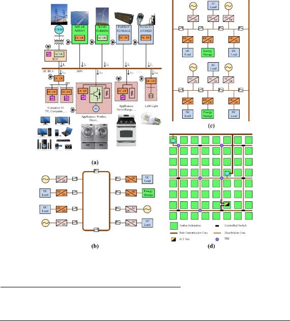
This type of distribution structure is the most simple and economical in terms of implementation. The DC bus runs from one end to another with the sources and loads connected anywhere depending on their location, as shown in Figure 1a. The reliability of the system is the least compared to other bus structures as a fault on the DC bus will result in the shutdown of the entire system.
Energies 2018, 11, 2463 |
3 of 20 |
Energies 2018, 11, x FOR PEER REVIEW |
4 of 21 |
Figure 1. DC bus structures: (a) radial; (b) ring; (c) ladder; (d) meshed.
( )
2.1.2. Ring Bus Structure |
|
|
|
|
Table 1. Advantages and disadvantages of different DC bus structures. |
|
|||
As the name suggests, in this configuration the DC bus is in the form of a ring. This bus structure |
||||
System Features |
Radial Bus |
Ring Bus |
Ladder Bus |
Meshed Bus |
is more expensive than the radial one as it involves more copper. It also has improved reliability at |
||||
Power Reliability |
Very Low |
Moderate |
High |
Very High |
increased cost. As seen in Figure 1b, the DC bus is divided into two sections using switchgear. Thus, |
||||
No. of Components |
Low |
Moderate |
High |
Very High |
when there is a fault on the DC bus, the switchgear can be used to isolate the faulted DC bus from |
||||
Cost |
Very Low |
Low |
Moderate |
Very High |
the un-faulted DC bus, thereby ensuring continuity in operation on the segment of the system with no2.2.faultPower. Architectures
In general, power architectures for a DC power system can be classified into centralized and
2.1.3. Ladder Bus Structure
distributed architectures [21,22]. The first DC power system introduced was a centralized
In this structure, the DC bus in the shape of a ladder increases the reliability of the system with an architecture. In this system architecture, the power was generated, processed, and controlled in one
increase in cost compared to the ring bus structure. Ladder bus structure is an extension of the ring centralized unit and delivered to loads through a network of power conductors or cables. The simple
structure with higher reliability. As seen in Figure 1c, when a fault occurs at any point in the system, block diagram representation of a centralized power system architecture is shown in Figure 2a. This
the faulted region of the bus can be isolated from the rest of the system using appropriate switchgear. type of system architecture is effective if the loads are all of a defined voltage level. As time
progressed, the number of loads with different voltage levels increased on the system and eventually,
2.1.4. Meshed Bus Structure
the centralized power architecture could no longer support the needs of the loads. As a result,
The meshed bus structure shown in Figure 1d is a modified ring bus structure obtained when distributed power system architecture was developed that powered the loads through number of
multiple ring structures are joined together. A system with meshed bus structure has the highest
PECs as shown in Figure 2b.
reliability compared to the other three structures. this structure is the most expensive of all
Distributed power system architecture compriseObviously,of different PECs, which provide different
as it requires more copper.
voltage level outputs catering power to various loads. With ever increasing power demand and loads at different voltage levels, distributed power system architecture gained acceptance, globally replacing the centralized power system architecture. By using smaller PECs, this architecture enables the use of standardized low power modules that make it easy to customize an existing system for any
Energies 2018, 11, 2463 |
4 of 20 |
It is observed that the higher the reliability requirement, the higher the cost of the system will be. Therefore, the selection of the bus structure is based on how reliable the system must be and how much one is willing to pay for it. For residential applications, where reliability is not a dictating factor, a simple radial bus structure can be implemented. One good example of a radial DC bus structure is the DC nanogrid architecture [16], where the renewable energy sources and storage systems are integrated along with the existing power grid. If an application demands even higher reliability, one can choose from ring, ladder, or meshed bus structures depending on the budget and level of desired reliability. Highly reliable ring, ladder or meshed structures can be seen in telecommunication systems and data centers. A comparison of the advantages and disadvantages of the four DC bus structures discussed in terms of reliability, number of components, and cost is presented in Table 1.
Table 1. Advantages and disadvantages of different DC bus structures.
System Features |
Radial Bus |
Ring Bus |
Ladder Bus |
Meshed Bus |
Power Reliability |
Very Low |
Moderate |
High |
Very High |
No. of Components |
Low |
Moderate |
High |
Very High |
Cost |
Very Low |
Low |
Moderate |
Very High |
|
|
|
|
|
2.2. Power Architectures
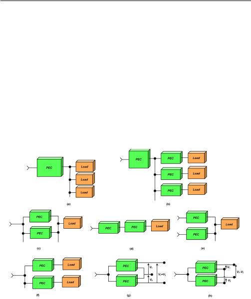
In general, power architectures for a DC power system can be classified into centralized and distributed architectures [21,22]. The first DC power system introduced was a centralized architecture. In this system architecture, the power was generated, processed, and controlled in one centralized unit and delivered to loads through a network of power conductors or cables. The simple block diagram representation of a centralized power system architecture is shown in Figure 2a. This type of system architecture is effective if the loads are all of a defined voltage level. As time progressed, the number of loads with different voltage levels increased on the system and eventually, the centralized power architecture could no longer support the needs of the loads. As a result, distributed power system architecture was developed that powered the loads through a number of PECs as shown in Figure 2b.
Energies 2018, 11, x FOR PEER REVIEW |
6 of 21 |
Figure 2. Power architectures: (a) |
(b) distributed. Distribution configuratio s: ( ) parallel; |
|
Figure 2. Power architectures: (a) |
centralized; (b) distributed. |
Distribution configurations: (c) |
(d) cascading; (e) source splitting; (f) load splitting; (g) sum stacking module; (h) difference stacking
parallel; (d) cascading; (e) source splitting; (f) load splitting; (g) sum stacking module; (h) difference module.
stacking module.
3. Efficiency
Efficiency improvement achieved using DC distribution systems compared to AC distribution systems can be attributed to various reasons. The main reason for higher efficiency of DC systems is it requires lower number of power conversion stages. In current architectures, the majority of residential and commercial loads comprise of electronic loads that require DC power. To supply these loads using a conventional AC distribution system, a power electronic converter is required to first convert AC to DC. This power conversion from AC to DC results in additional power losses, usually about 4–15% of the input power; assuming the converters are 85–96% efficient. Therefore, the total
Energies 2018, 11, 2463 |
5 of 20 |
Distributed power system architecture comprises of different PECs, which provide different voltage level outputs catering power to various loads. With ever increasing power demand and loads at different voltage levels, distributed power system architecture gained acceptance, globally replacing the centralized power system architecture. By using smaller PECs, this architecture enables the use of standardized low power modules that make it easy to customize an existing system for any special requirements in the future. PECs can be made more efficient with increased power density by operating at high frequencies, as they are required to handle low power. Higher reliability can be achieved by isolating a fault on one module and keeping the rest of the system unaffected. The various merits of distributed power architecture can be attributed to five basic configurations that are used in order to supply specific loads. They are as follows:
2.2.1. Paralleling
In a paralleling configuration shown in Figure 2c, instead of using a single high power module, multiple low power PEC modules are connected in parallel to supply the load. Since a module processes part of the power, it experiences reduced thermal and electrical stresses, making the overall system more reliable even on increased component count. Individual modules can be reduced in size, cost, and made with a higher power density by operating at higher frequencies. This configuration provides simple maintenance and high reliability using redundancy (using ‘n+1’ modules instead of required ‘n’ modules).
2.2.2. Cascading
In a cascaded configuration shown in Figure 2d, an intermediate bus is introduced into the power conversion of high voltage to a low voltage, which reduces power transformation losses. Also, distribution efficiency is improved when the converter is placed close to the load. The intermediate bus can be used for energy storage integration, improving the reliability and power quality. Cascaded units can be used for different purposes that are difficult to supply by a single converter. An example of such a cascaded configuration is a rectifier cascaded with a DC–DC converter where the rectifier can be used to achieve unity power factor and the DC–DC converter can be utilized for load voltage regulation.
2.2.3. Source Splitting
Source splitting configuration as shown in Figure 2e, enables the use of multiple sources to supply one load. The power redundancy and simple battery backup feature improves the power quality and reliability of this system.
2.2.4. Load Splitting
In load splitting configuration, as shown in Figure 2f, loads are supplied using multiple PECs. This configuration provides better load regulation, which can be difficult to achieve using a single centralized PEC because of the bus impedance. Moreover, this configuration allows selective battery backup for critical loads, which reduces the size and cost of batteries used in the system. Also, as different loads are supplied from separate sources, noise interference is reduced.
2.2.5. Stacking
Stacking configuration of PECs is mainly used to achieve desired output voltage levels by combining the outputs of multiple units. By stacking standardized units, non-standardized outputs can be obtained. For high voltage loads, the outputs of different PECs can be added as shown in Figure 2g. When a smaller voltage than standardized voltage is required, the difference of outputs can be obtained by connecting the outputs as shown in Figure 2h.