Page 1292 |
DICOM PS3.3 2020a - Information Object Definitions |
C.10.10.1 Waveform Annotation Attribute Descriptions
C.10.10.1.1 Referenced Channels
Referenced Waveform Channels (0040,A0B0) is a multi-value Attribute that lists the channels to which an annotation of a waveform applies. Each channel is specified as a pair of values (M,C), where the first value is the ordinal of the Item of Waveform Sequence (5400,0100) (i.e., the Multiplex Group Number), and the second value is the ordinal of the Item of the Channel Definition Sequence (003A,0200) Attribute (i.e., the Waveform Channel Number) within the multiplex group.
If the specified channel number is 0, the annotation applies to all channels in the multiplex group.
Note
As an example, an annotation that applies to the entire first multiplex group and channels 2 and 3 of the third multiplex group would have Referenced Channels value 0001 0000 0003 0002 0003 0003.
C.10.10.1.2 Temporal Range Type
The Temporal Range Type (0040,A130) Attribute defines the type of temporal extent of the annotated region of interest. A temporal point (or instant of time) may be defined by a waveform sample offset (for a single waveform multiplex group only), time offset, or absolute time.
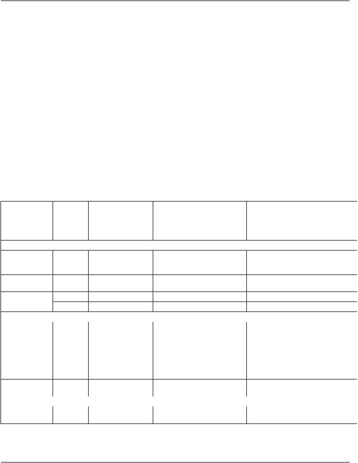
Enumerated Values:
POINT |
a single temporal point |
MULTIPOINT |
multiple temporal points |
SEGMENT |
a range between two temporal points |
MULTISEGMENTmultiple segments, each denoted by two temporal points |
BEGIN |
a range beginning at one temporal point, and extending beyond the end of the acquired data |
END |
a range beginning before the start of the acquired data, and extending to (and including) the identified temporal |
|
point |
C.10.10.1.3 Referenced Sample Positions
Referenced Sample Positions (0040,A132) may be used only if Referenced Waveform Channels (0040,A0B0) refers to channels within a single multiplex group. The sample position is by channel, and applies to all channels specified in Referenced Channels (0040,A0B0).
C.10.10.1.4 Annotation Group Number
The Annotation Group Number (0040,A180) allows the logical association of multiple annotations within the current SOP Instance. Such linked annotations share an Annotation Group Number, but each annotation is semantically separable. The nature of the asso- ciation is not defined. The number is not semantically significant.
Note
For instance, the R-wave in several waveform channels may be annotated, and all occurrences of the same R-wave could be linked in an annotation group.
C.10.11 Graphic Group Module
Graphic Group Module provides the label and description for the logical associations made by the Graphic Group ID (0070,0295) of graphic objects.
The grouping concept used in the Graphic Group Module differs from the grouping concept used in the Graphic Layer Module. GraphicLayerModuleaddressestherenderingorderbyusingtheGraphicLayerOrder(0070,0062),whichspecifieswhichannotations arerenderedfirst.TheGraphicGroupModuleisusedtospecifywhichannotationsbelongtogetherandshallbehandledtogether(e.g., rotate, move) independent of the Graphic Layer to which they are assigned.

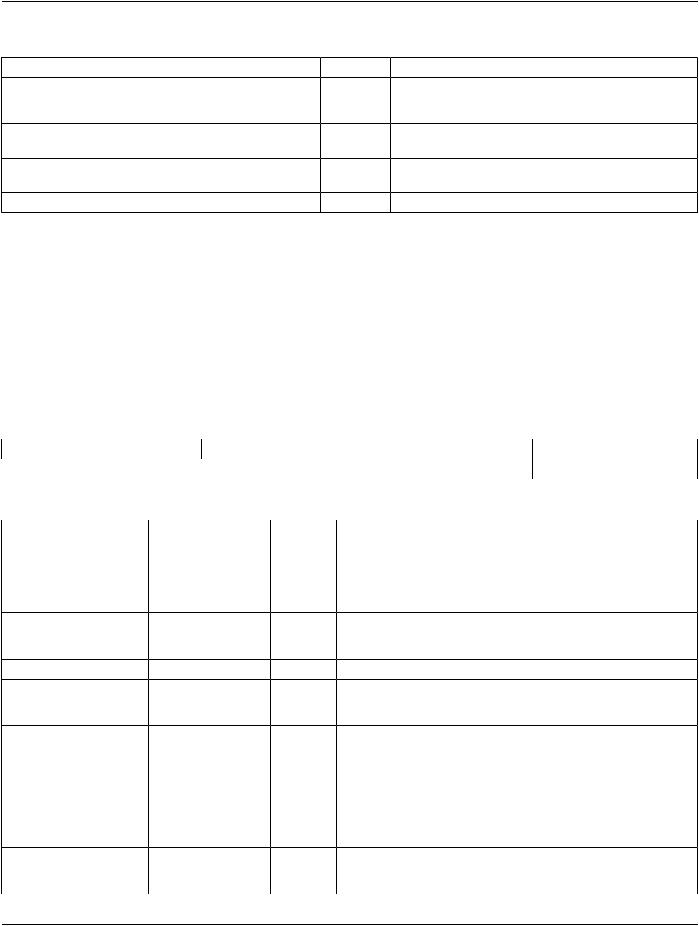
 Include Table C.11-1b “Modality LUT Macro Attributes”