DICOM PS3.3 2020a - Information Object Definitions |
Page 1273 |
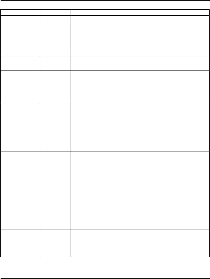
TOP - ticks are aligned to the upper part of the line, where the first point of the line is on the left and the line extends horizontally to the right.
Tick Label Alignment (0070,0279) defines the alignment of the tick labels.
BOTTOM - labels are aligned to the lower part of the line, where the first point of the line is on the left and the line extends horizontally to the right.
TOP - labels are aligned to the upper part of the line, where the first point of the line is on the left and the line extends horizontally to the right.
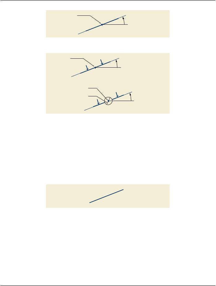
The presence, labeling and units of the ticks on the line is application dependent(see Figure C.10.5-7). If present as numerical values, the labels of the ticks shall increase toward the second point.
C.10.5.1.3.9 Axis
For the Compound Graphic Type (0070,0294) AXIS, exactly two points shall be present inside Graphic Data (0070,0022) defining the axis line.
Major Tick |
|
|
2 |
|
|
|
|
1 |
|
|
|
|
|
|
|
Minor Tick |
0 |
|
|
Second Point |
|
|
|
-1 |
|
|
|
|
-2 |
|
|
|
First Point |
|
|
|
|
|
|
|
|
|
|
Figure C.10.5-7. RULER / AXIS Example Showing TOP Tick Alignment and TOP Tick Label Alignment
The Major Ticks Sequence (0070,0287) specifies the placement and label of the ticks. The rendering of the minor ticks is left to the application.
Tick Alignment (0070,0274) defines the alignment of the ticks.
BOTTOM - ticks are aligned to the lower part of the line, where the first point of the line is on the left and the line extends horizontally to the right.
CENTER - ticks are centered on the line.
TOP - ticks are aligned to the upper part of the line, where the first point of the line is on the left and the line extends horizontally to the right.
Tick Label Alignment (0070,0279) defines the alignment of the tick labels.
BOTTOM - labels are aligned to the lower part of the line, where the first point of the line is on the left and the line extends horizontally to the right.
TOP - labels are aligned to the upper part of the line, where the first point of the line is on the left and the line extends horizontally to the right.
C.10.5.1.3.10 Crosshairs
For Compound Graphic Type (0070,0294) CROSSHAIR, exactly one point shall be present inside Graphic Data (0070,0022). This point is the origin of the CROSSHAIR (see Figure C.10.5-8).
Tick Alignment (0070,0274) and Tick Label Alignment (0070,0279) are also valid for the CROSSHAIR. Tick rendering is application dependent.

 Second Point

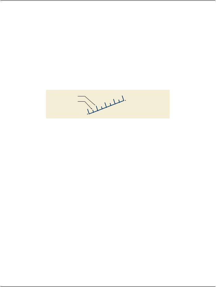

 Anchor Point