Материал: part03

Внимание! Если размещение файла нарушает Ваши авторские права, то обязательно сообщите нам

Page 786​

DICOM PS3.3 2020a - Information Object Definitions​

Attribute Name​

Tag​

Type​


Attribute Description​

>>Table Top Eccentric​

(300A,0126)​

1C​

Direction of Table Top Eccentric Rotation when viewing table from​

Rotation Direction​


above, for segment beginning at current Control Point. Required for​


Control Point 0 of Control Point Delivery Sequence (3008,0040) or if​


Table Top Eccentric Rotation Direction changes during beam​


administration.​


Enumerated Values:​


CW​ clockwise​


CC​

counter-clockwise​


NONE​no rotation​

>>Table Top Pitch Angle​

(300A,0140)​

1C​

Table Top Pitch Angle, i.e., the rotation of the IEC TABLE TOP​


coordinate system about the X-axis of the IEC TABLE TOP coordinate​


system (degrees). If required by treatment delivery device, shall be​


presentforfirstItemofControlPointSequence.Ifrequiredbytreatment​


delivery device and if Table Top Pitch Angle changes during Beam,​


shallbepresentinallsubsequentItemsofControlPointSequence.See​


Section C.8.8.25.6.2.​

>>Table Top Pitch Rotation​

(300A,0142)​

1C​

Direction of Table Top Pitch Rotation when viewing the table along the​

Direction​


positive X-axis of the IEC TABLE TOP coordinate system, for segment​


following Control Point. If required by treatment delivery device, shall​


be present for first Item of Control Point Sequence. If required by​


treatment delivery device and if Table Top Pitch Rotation Direction​


changesduringBeam,shallbepresentinallsubsequentItemsofControl​


Point Sequence. See Section C.8.8.14.8 and Section C.8.8.25.6.2.​


Enumerated Values:​


CW​ clockwise​


CC​

counter-clockwise​


NONE​no rotation​

>>Table Top Roll Angle​

(300A,0144)​

1C​

TableTopRollAngle,i.e.,therotationoftheIECTABLETOPcoordinate​


system about the IEC Y-axis of the IEC TABLE TOP coordinate system​


(degrees). If required by treatment delivery device, shall be present for​


first Item of Control Point Sequence. If required by treatment delivery​


device and if Table Top Roll Angle changes during Beam, shall be​


present in all subsequent Items of Control Point Sequence. See​


Section C.8.8.25.6.2.​

>>Table Top Roll Rotation​

(300A,0146)​

1C​

Direction of Table Top Roll Rotation when viewing the table along the​

Direction​


positive Y-axis of the IEC TABLE TOP coordinate system, for segment​


following Control Point. If required by treatment delivery device, shall​


be present for first Item of Control Point Sequence. If required by​


treatment delivery device and if Table Top Roll Rotation Direction​


changesduringBeam,shallbepresentinallsubsequentItemsofControl​


Point Sequence. See Section C.8.8.14.8 and Section C.8.8.25.6.2.​


Enumerated Values:​


CW​ clockwise​


CC​

counter-clockwise​


NONE​no rotation​

>>TableTopVerticalPosition​

(300A,0128)​

2C​

TableTopVerticalpositioninIECTABLETOPcoordinatesystem(mm).​


This value is interpreted as an absolute, rather than relative, Table​


setting.RequiredforControlPoint0ofControlPointDeliverySequence​


(3008,0040) or if Table Top Vertical Position changes during beam​


administration.​

- Standard -​


DICOM PS3.3 2020a - Information Object Definitions​

Page 787​

Attribute Name​

Tag​

Type​

Attribute Description​


>>Table Top Longitudinal​

(300A,0129)​

2C​

Table Top Longitudinal position in IEC TABLE TOP coordinate system​

Position​


(mm).Thisvalueisinterpretedasanabsolute,ratherthanrelative,Table​


setting.RequiredforControlPoint0ofControlPointDeliverySequence​


(3008,0040)or if TableTop LongitudinalPositionchanges during beam​


administration.​


>>Table TopLateralPosition​

(300A,012A)​

2C​

TableTopLateralpositioninIECTABLETOPcoordinatesystem(mm).​


This value is interpreted as an absolute, rather than relative, Table​


setting.RequiredforControlPoint0ofControlPointDeliverySequence​


(3008,0040) or if Table Top Lateral Position changes during beam​


administration.​


>>Corrected Parameter​

(3008,0068)​

3​

A Sequence of Items describing any corrections made to any Attributes​

Sequence​


prior to delivery of the next control point.​


One or more Items are permitted in this Sequence.​


>>>Parameter Sequence​

(3008,0061)​

1​

Contains the Data Element Tag of the parent Sequence containing the​

Pointer​


Attribute that was corrected.​


ThevalueislimitedinscopetotheTreatmentSessionBeamSequence​


(3008,0020) and all nested Sequences therein.​


>>>Parameter Item Index​

(3008,0063)​

1​

Contains the Sequence Item index (starting at 1) of the corrected​


Attribute within its parent Sequence.​


>>>Parameter Pointer​

(3008,0065)​

1​

Contains the Data Element Tag of the Attribute that was corrected.​

>>>Correction Value​

(3008,006A)​

1​

ThevalueappliedtotheAttributethatwasreferencedbytheParameter​


SequencePointer(3008,0061),ParameterItemIndex(3008,0063)and​


Parameter Pointer (3008,0065).​


>>Override Sequence​

(3008,0060)​

3​

Sequenceofparametersthatwereoverriddenduringtheadministration​


of the beam segment immediately prior to the current control point.​


One or more Items are permitted in this Sequence.​


>>>Override Parameter​

(3008,0062)​

2​

Contains the Data Element Tag of the Attribute that was overridden.​

Pointer​


>>>Parameter Sequence​

(3008,0061)​

3​

Contains the Data Element Tag of the parent Sequence containing the​

Pointer​


Attribute that was overridden. The value is limited in scope to the​


Treatment Session Beam Sequence (3008,0020) and all nested​


Sequences therein.​


>>>Parameter Item Index​

(3008,0063)​

3​

Contains the Sequence Item index (monotonically increasing from 1) of​


theoverriddenAttributeswithinitsparentSequence.Thevalueislimited​


in scope to the Treatment Session Beam Sequence (3008,0020) and​


all nested Sequences therein.​


>>>ParameterValueNumber​

(3008,0067)​

3​

Positive integer identifying which value of a multi-valued Attribute​


identifiedbyOverrideParameterPointer(3008,0062)isreferenced.The​


value 1 identifies the first value.​


>>>Operators' Name​

(0008,1070)​

2​

Name of operator who authorized override.​


>>>Operator Identification​

(0008,1072)​

3​

Identificationoftheoperatorwhoauthorizedoverride.OnlyasingleItem​

Sequence​


is permitted in this Sequence.​


>>>>Include Table 10-1 “Person Identification Macro​ Attributes Description”​

>>>Override Reason​

(3008,0066)​

3​

User-defined description of reason for override of parameter specified​ by Override Parameter Pointer (3008,0062).​

- Standard -​

Page 788​

DICOM PS3.3 2020a - Information Object Definitions​

C.8.8.21.1 Control Point Machine Delivery Parameters​

All treatment machine delivery parameters (including table angles and positions) in the RT Treatment Session Record Module shall​ be specified as absolute, not relative, values at the Control Point.​

C.8.8.21.2 Specified and Delivered Meterset Values​

C.8.8.21.2.1 Beam Level​

ThevalueofSpecifiedPrimaryMeterset(3008,0032)shallbethevaluespecifiedbyBeamMeterset(300A,0086)inthecorresponding​ Fraction Group of the referenced RT Plan. The referenced RT Plan is found in the Referenced RT Plan Sequence (300C,0002), and​ within this plan the Fraction Group is found using the Referenced Fraction Group Number (300C,0022) in this Module. The Beam is​ found in the referenced RT Plan using the Referenced Beam Number (300C,0006) in the same Item of the Treatment Session Beam​ Sequence (3008,0020) as the Specified Primary Meterset (3008,0032).​

The value of Delivered Primary Meterset (3008,0036) shall be the accumulated value of the delivered Meterset across all Control​ Points, which is recorded in this Item of the Treatment Session Beam Sequence (3008,0020).​

Note that, for example, when a partial treatment has occurred and resumption(s) have been delivered that complete delivery of all​ control points remaining, the sum of the Delivered Primary Meterset (3008,0036) values in all RT Beams Session Records for the​ beam in question and the fraction being treated will match the specified Meterset for the whole fraction.​

C.8.8.21.2.2 Control Point Level​

Specified Meterset (3008,0042) contains the MU as specified in the corresponding RT Plan at a given control point.​

Delivered Meterset (3008,0044) shall contain one of the following three values:​

•​the Meterset value at which the delivery of the current beam started​

•​the Specified Meterset​

•​the Meterset value at which the delivery of the current beam ended​

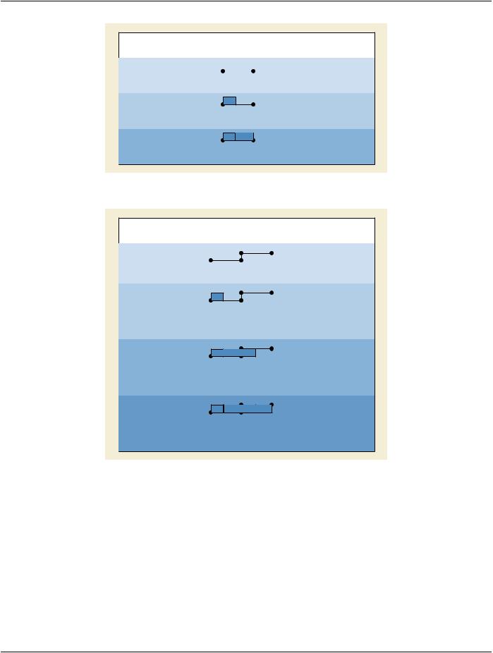
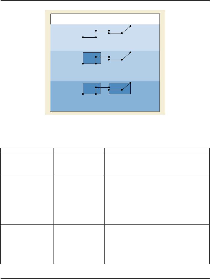
Control points that already have been treated in an earlier session shall contain the Meterset value at which the delivery of the current​ beam started. Control points that have been completely treated during the current session shall contain the Specified Meterset value​ for this Control Point. Control Points that have not yet been treated or not completely shall contain the total delivered MU up to the​ point where the interruption has occurred (i.e., the last control point treated).​

This can be expressed by the following equation:​

DelMS[CPn] = MAX (StartMS, MIN (SpecMS[CPn], EndMS))​

with​

DelMS[CPn]​ Delivered Meterset value at control point n​

SpecMS[CPn]​Specified Meterset value at control point n​

StartMS​ Meterset value where delivery of current beam started​

EndMS​ Meterset value where delivery of current beam ended​

By this definition it is unambiguously recorded, which 'segments' of control points have been delivered in case of partial treatments.​

- Standard -​

DICOM PS3.3 2020a - Information Object Definitions​

Page 789​

Example 1: 2 Control Points, 2 complete Partial Treatments Total Meterset: 50

Interruption at: 18 MU

RT Plan:


0


1


Cumulative Meterset Weight:

0.0

1.0

RT Treatment Record 1 of 2

Specified Meterset:

Delivered Meterset:

0

1

0

50

Delivered MU:

18

0

18


RT Treatment Record 2 of 2

Specified Meterset:

Delivered Meterset:

0

1

0

50

Delivered MU:

32

18

50


Figure C.8.8.21-1. Control Point Example 1: 2 Control Points, 2 Complete Partial Treatments​

Example 2: 4 Control Points, 3 complete Partial Treatments

Total Meterset: 50

Interruption at: 25, 30 MU

RT Plan:


0

Cumulative Meterset Weight:

0.0

2

3


IN

1

OUT


0.6

1.0

0.6


RT Treatment Record 1 of 3

Specified Meterset:

Delivered Meterset:


2

3

IN


0

1


OUT


0

30

50

Delivered MU:

25


30


Wedge Dose:

0.0 (0 MU)

0

25

25


25


RT Treatment Record 2 of 3

Specified Meterset:

Delivered Meterset:


2

3

IN


0

1


OUT


0

30

50

Delivered MU:

20


30


Wedge Dose:

0.75 (15 MU)

25

30

45


30


RT Treatment Record 3 of 3

Specified Meterset:

Delivered Meterset:

2

0

1

030

30

4545

45

3

IN


OUT


50

Delivered MU:

5


Wedge Dose:

1.0 (5 MU)

50


Figure C.8.8.21-2. Control Point Example 1: 2 Control Points, 2 Complete Partial Treatments​

- Standard -​

Page 790​

DICOM PS3.3 2020a - Information Object Definitions​

Example 3: 7 Control Points, 2 Partial Treatments with small gap

Total Meterset: 50

Interuption at: 25 MU, Resumption at 30 MU

RT Plan:

0

Cumulative Meterset Weight: 0.0

2

3

4

1

0.30.6

0.30.6

6

5

1.0

0.8

RT Treatment Record 1 of 2

0

Specified Meterset:

0

Delivered Meterset:

0

2

3

4

1

15

30

15

30

15

25

15

25

6

5

50 Delivered MU: 25

40

25

40

RT Treatment Record 1 of 2

0

Specified Meterset:

0

Delivered Meterset:

30

2

3

6


4

5

1


15

30

50

Delivered MU: 20

15

30

40


30

30

50


30

30

40


Figure C.8.8.21-3. Control Point Example 3: 7 Control Points, 2 Partial Treatments with Small Gap​

C.8.8.22 RT Brachy Session Record Module​

Table C.8-58. RT Brachy Session Record Module Attributes​

Attribute Name​

Tag​

Type​

Attribute Description​

Referenced Fraction Group​

(300C,0022)​

3​ Identifier of Fraction Group within referenced RT Plan.​

Number​


Number of Fractions Planned​

(300A,0078)​

2​ Totalnumberoftreatments(Fractions)plannedforcurrentFraction​


Group.​

Brachy Treatment Technique​

(300A,0200)​

1​ Type of brachytherapy treatment technique.​

Enumerated Values:​

INTRALUMENARY​

INTRACAVITARY​

INTERSTITIAL​

CONTACT​

INTRAVASCULAR​

PERMANENT​

See RT Plan IOD.​

Brachy Treatment Type​

(300A,0202)​

1​ Type of brachytherapy treatment.​

Defined Terms:​

MANUAL​Manually positioned​

HDR​ High dose rate​

MDR​ Medium dose rate​

LDR​ Low dose rate​

PDR​ Pulsed dose rate​

- Standard -​