Материал: part03

Внимание! Если размещение файла нарушает Ваши авторские права, то обязательно сообщите нам


DICOM PS3.3 2020a - Information Object Definitions​

Page 691​

Attribute Name​

Tag​

Type​

Attribute Description​


Vertices of the Polygonal​

(0018,1720)​

1C​

Required if a value of Collimator Shape (0018,1700) is POLYGONAL.​

Collimator​


Multiple Values where the first set of two values are:​


row of the origin vertex;​

column of the origin vertex.​

Twoormorepairsofvaluesfollowandaretherowandcolumncoordinates​ of the other vertices of the polygon collimator. Polygon collimators are​ implicitly closed from the last vertex to the origin vertex and all edges shall​ be non-intersecting except at the vertices.​

C.8.7.3.1 X-Ray Collimator Attribute Descriptions​

C.8.7.3.1.1 Collimator Vertical and Horizontal Edges​

These Attributes specify the pixel row or column where the X-Ray beam is fully obscured by a rectangular collimator:​

•​if the left edge of the collimator is not visible, Collimator Left Vertical Edge (0018,1702) shall have a value of 0;​

•​if the right edge of the collimator is not visible, Collimator Right Vertical Edge (0018,1704) value shall be 1 greater than the value​ of Columns (0028,0011) Attribute;​

•​if the top edge of the collimator is not visible, Collimator Upper Horizontal Edge (0018,1706) shall have a value of 0;​

•​if the bottom edge of the collimator is not visible, Collimator Lower Horizontal Edge (0018,1708) value shall be 1 greater than the​ value of Rows (0028,0010) Attribute.​

C.8.7.4 X-Ray Table Module​

Table C.8-29 contains Attributes that describe X-Ray images acquired with movement of the patient imaging table.​

Table C.8-29. X-Ray Table Module Attributes​

Attribute Name​

Tag​

Type​

Attribute Description​

Table Motion​

(0018,1134)​

2​

Defined Terms:​


STATIC​


DYNAMIC​

Table Vertical Increment​

(0018,1135)​

2C​

IncrementalchangeinVerticalpositionofthetablerelativetofirstframe​


of Multi-frame image given in mm.​


Required if Table Motion is DYNAMIC.​

Table Longitudinal​

(0018,1137)​

2C​

Incremental change in Longitudinal position of the table relative to first​

Increment​


frame of Multi-frame image in mm. Table motion towards +90°position​


oftheprimaryangleofthepositionerispositive.SeeSectionC.8.7.4.1.2.​


Required if Table Motion is DYNAMIC.​

Table Lateral Increment​

(0018,1136)​

2C​

Incremental change in Lateral position of the table relative to first frame​


of Multi-frame image given in mm. Table motion towards +90°position​


of the secondary angle of the positioner is positive. See​


Section C.8.7.4.1.3.​


Required if Table Motion is DYNAMIC.​

Table Angle​

(0018,1138)​

3​

Angle of table plane in degrees relative to horizontal plane [Gravity​


plane]. Positive values indicate that the head of the table is upwards.​

- Standard -​

Page 692​

DICOM PS3.3 2020a - Information Object Definitions​

C.8.7.4.1 X-Ray Table Attribute Descriptions​

C.8.7.4.1.1 Table Motion Increments​

This section is replaced by Section C.8.7.4.1.4​

C.8.7.4.1.2 Table Longitudinal Increment​

The direction of the longitudinal movement is perpendicular to the primary axis of rotation of the positioner. A positive value of Table​ Longitudinal Increment (0018,1137) Attributes indicates a movement towards the +90° position of the positioner, see Figure C.8-9a.​

Table Longitudinal

Direction

+90º

-90º

Positioner Primary Axis of

Rotation

Figure C.8-9a. Table Longitudinal Movement​

C.8.7.4.1.3 Table Lateral Increment​

The direction of the lateral movement is perpendicular to the secondary axis of rotation of the positioner. A positive value of Table​ Lateral Increment (0018,1136) Attributes indicates a movement towards the +90° position of the positioner, see Figure C.8-9b.​

Table Lateral

Direction

+90º

-90º

Positioner Secondary Axis of

Rotation

Figure C.8-9b. Table Lateral Movement​

Note​

The terms "longitudinal" and "lateral" are relative to an operator standing tableside, and facing the patient. Thus lateral​ movement is to the left and right of the operator, and longitudinal movement is towards or away from the operator.​

C.8.7.4.1.4 Table Motion With Patient in Relation to Imaging Chain​

The table moves the patient with respect to the imaging chain. This is being tracked as a motion of the imaging chain with respect to​ a coordinate system (X, Y, Z) attached to the patient (assumption is that the patient does not move with respect to the table). The​ coordinate system origin is fixed with respect to the patient at the time of the first frame. The X-axis is increasing to the left hand side​ of the patient. The Y-axis is increasing to the posterior side of the patient. The Z-axis is increasing toward the head of the patient (see​ Section C.7.6.2.1.1). The Patient Plane is then defined by the X and Z-axes as drawn in Figure C.8-10).​

- Standard -​

DICOM PS3.3 2020a - Information Object Definitions​

Page 693​

Note​

1.​Tablemotioncausestheapparentlocusofimagingtomoveintheoppositedirection.Forinstance,withthepatientsupine​ and the table motion towards +90°of the primary axis of rotation of the positioner, the area of the patient imaged moves​ toward the right hand side of the patient.​

2.​Whenthepatientispositionedproneorsupine(FigureC.8-2showingthesupineposition)theTableLongitudinalIncrement​ (0018,1137) table motion takes place along the patient X-axis and the Table Lateral Increment (0018,0036) along the​ Z-axis. For patient positioned left or right decubitus, the Table Longitudinal Increment takes place along the Y-axis, the​ other direction is not changed.​

+Z

+X

Patient Plane


+Y

Figure C.8-10. Table Motion Vector Coordinates​

C.8.7.5 XA Positioner Module​

Table C.8-30 contains IOD Attributes that describe a c-arm positioner typically used in acquiring X-Ray Angiographic Images. The​ coordinate system used to track the positioner is defined in reference to the patient. The definition of coordinates with respect to the​ equipment is not supported. Furthermore, this Module does not describe the movement of the patient.​

Note​

The scope of the XA IOD is to address images produced on acquisition equipment equipped with an X-Ray source and an​ image Receptor positioned by what is general called a c-arm. For clinical areas other than Angiography that are using a c-​ arm to position the X-Ray source and image receptor (e.g., Interventional Procedures and Myelography and Biopsy/Localiz-​ ation), the X-Ray Angiography Image Object should be also used. Although the object is optimized for c-arm systems, it may​ also be used by other systems that support a similar coordinate system, such as some RF systems.​

Table C.8-30. XA Positioner Module Attributes​

Attribute Name​

Tag​

Type​

Attribute Description​

Distance Source to Patient​

(0018,1111)​

3​ Distance in mm from source to center of field of view.​


Note​


1.​This value is traditionally referred to as Source Object​


Distance (SOD).​


2.​For cardiovascular image equipment the SOD value​


typically is the distance from source to isocenter.​

Distance Source to Detector​

(0018,1110)​

3​ Distance in mm from source to detector center.​


Note​


This value is traditionally referred to as Source Image Receptor​


Distance (SID).​

Estimated Radiographic​

(0018,1114)​

3​ Ratio of Source Image Receptor Distance (SID) over Source Object​

Magnification Factor​


Distance (SOD).​

- Standard -​

Page 694​

DICOM PS3.3 2020a - Information Object Definitions​

Attribute Name​

Tag​

Type​

Attribute Description​

Positioner Motion​

(0018,1500)​

2C​

Used to describe the activity of the imaging devices.​


Defined Terms:​


DYNAMIC​


STATIC​


See Section C.8.7.5.1.1.​


Required if Pixel Data (7FE0,0010) contains more than one frame. May​


be present otherwise.​

Positioner Primary Angle​

(0018,1510)​

2​

Position of the X-Ray Image Intensifier about the patient from the RAO​


to LAO direction where movement from RAO to vertical is positive.​


See Section C.8.7.5.1.2.​

Positioner Secondary Angle​

(0018,1511)​

2​

Position of the X-Ray Image Intensifier about the patient from the CAU​


to CRA direction where movement from CAU to vertical is positive.​


See Section C.8.7.5.1.2​

Positioner Primary Angle​

(0018,1520)​

2C​

Incremental change in primary positioner angle for each frame.​

Increment​


See Section C.8.7.5.1.3.​


Required if Positioner Motion (0018,1500) equals DYNAMIC.​

Positioner Secondary Angle​

(0018,1521)​

2C​

Incremental change in secondary positioner angle for each frame.​

Increment​


See Section C.8.7.5.1.3.​


Required if Positioner Motion (0018,1500) equals DYNAMIC.​

Detector Primary Angle​

(0018,1530)​

3​

Angle of the X-Ray beam in the row direction in degrees relative to the​


normal to the detector plane. Positive values indicate that the X-Ray​


beamistiltedtowardshighernumberedcolumns.Negativevaluesindicate​


that the X-Ray beam is tilted towards lower numbered columns.​


See Section C.8.7.5.1.4.​

Detector Secondary Angle​

(0018,1531)​

3​

Angle of the X-Ray beam in the column direction in degrees relative to​


the normal to the detector plane. Positive values indicate that the X-Ray​


beam is tilted towards lower numbered rows. Negative values indicate​


that the X-Ray beam is tilted towards higher numbered rows.​

See Section C.8.7.5.1.4.​

C.8.7.5.1 XA Positioner Attribute Descriptions​

C.8.7.5.1.1 Positioner Motion​

PositionerMotion(0018,1500)AttributeisSTATICiftheimagingtablemovesduringamulti-frameacquisition,buttheX-Raypositioner​ do not move.​

If Pixel Data (7FE0,0010) contains a single frame and a value of Positioner Motion (0018,1500) is provided, the value shall be​ STATIC.​

Note​

If the positioner undergoes translation (non-rotational movement) during the acquisition, then that motion shall be described​ by an opposite table motion (see Section C.8.7.4).​

- Standard -​

DICOM PS3.3 2020a - Information Object Definitions​

Page 695​

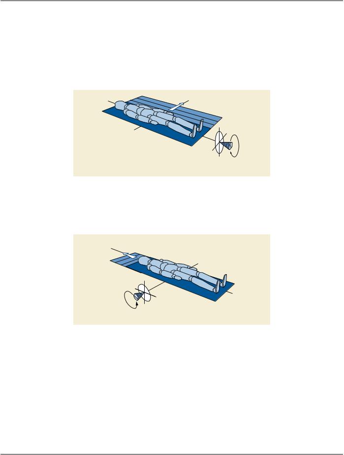
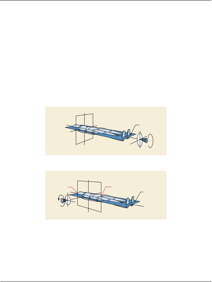
C.8.7.5.1.2 Positioner Primary and Secondary Angles​

The definitions of Positioner Angles shall be with respect to the patient as illustrated in Figure C.8-11 and Figure C.8-12. Zero degree​ is referenced to the origin perpendicular to the patient's chest. The Positioner Primary Angle definition is like longitude (in the equat-​ orial plan); the Positioner Secondary Angle definition is like latitude (in the sagittal plane). The Positioner Angle Attributes apply to​ the first frame of a multi-frame image. The valid range of Primary Positioner Angle is -180 to +180 degrees and the Secondary Posi-​ tioner Angle range is -90 to + 90 degrees.​

The Patient Plane is defined by the isocenter of the imaging device and slices through the patient such that it is perpendicular to the​ sagittal plane of the body. The Primary Axis of rotation is defined at the intersection of the Patient Plane and of the Sagittal Plane.​ The Positioner Primary Angle is defined in the transaxial plane at the isocenter with zero degrees in the direction perpendicular to​ the patient's chest and + 90 degrees at the patient left hand side (LAO) and -90 at the patient right hand side (RAO). The valid range​ of Primary Positioner Angle is -180 to +180 degrees.​

The Secondary Axis is in the Patient Plane and is perpendicular to the Primary Axis at the isocenter. The Positioner Secondary Angle​ is defined in the Sagittal Plane at the isocenter with zero degrees in the direction perpendicular to the patient's chest. +90 degrees​ corresponds to the cranial direction. The Secondary Positioner Angle range is -90 to + 90 degrees.​

At a 0 angle for both Primary Angle (0018,1510) and Secondary Angle (0018,1511), the patient faces the Image Intensifier or digital​ detector.​

The Positioner Primary Angle (0018,1510) and Secondary Angle (0018,1511) apply to the first frame of a multi-frame image.​

LAO = +90º

Patient Plane

RAO = -90º

±180º Axis of Rotation

Figure C.8-11. Positioner Primary Angle​

CRA = +90º

CAU = -90º

Patient Plane

Axis of Rotation

Figure C.8-12. Positioner Secondary Angle​

C.8.7.5.1.3 Positioner Angle Increments​

If the positioner angles change during acquisition of a multi-frame image, the Positioner Angle Increment Attributes describe the an-​ gular change per frame.​

If the change in positioner angle is nominally constant for each frame, these fields may contain a single value of the average angular​ change per frame. Alternatively, the fields may contain a vector of offsets from the (initial) Positioner Angle Attributes, with one value​ for each frame in the multi-frame image. The number of values in the Positioner Angle Increment Attributes must be one, or must be​ equal to Number of Frames (0028,0008) in the Multi-frame Module (see Section C.7.6.6).​

- Standard -​