Материал: part03

Внимание! Если размещение файла нарушает Ваши авторские права, то обязательно сообщите нам

Page 606​

DICOM PS3.3 2020a - Information Object Definitions​

Attribute Name​

Tag​

Type​

Attribute Description​

>Red Palette Color Lookup​

(0028,1101)​

1C​

Specifies the format of the Red Palette Color Lookup Table Data​

Table Descriptor​


(0028,1201).​


The second value (first stored pixel value mapped) shall be zero.​


Required if RGB LUT Transfer Function (0028,140F) is TABLE.​

>GreenPaletteColorLookup​

(0028,1102)​

1C​

Specifies the format of the Green Palette Color Lookup Table Data​

Table Descriptor​


(0028,1202).​


The second value (first stored pixel value mapped) shall be zero.​


Required if RGB LUT Transfer Function (0028,140F) is TABLE.​

>Blue Palette Color Lookup​

(0028,1103)​

1C​

Specifies the format of the Blue Palette Color Lookup Table Data​

Table Descriptor​


(0028,1203).​


The second value (first stored pixel value mapped) shall be zero.​


Required if RGB LUT Transfer Function (0028,140F) is TABLE.​

>AlphaPaletteColorLookup​

(0028,1104)​

1C​

Specifies the format of the Alpha Palette Color Lookup Table Data.​

Table Descriptor​


The second value (first stored pixel value mapped) shall be zero.​


Required if Alpha LUT Transfer Function (0028,1410) is TABLE.​

>Red Palette Color Lookup​

(0028,1201)​

1C​

Red Palette Color Lookup Table Data.​

Table Data​


Required if RGB LUT Transfer Function (0028,140F) is TABLE.​


>GreenPaletteColorLookup​

(0028,1202)​

1C​

Green Palette Color Lookup Table Data.​

Table Data​


Required if RGB LUT Transfer Function (0028,140F) is TABLE.​


>Blue Palette Color Lookup​

(0028,1203)​

1C​

Blue Palette Color Lookup Table Data.​

Table Data​


Required if RGB LUT Transfer Function (0028,140F) is TABLE.​


>AlphaPaletteColorLookup​

(0028,1204)​

1C​

Alpha LUT contains the blending values for the data frames.​

Table Data​


Required if Alpha LUT Transfer Function (0028,1410) is TABLE.​


ICC Profile​

(0028,2000)​

1C​

An ICC Profile encoding the transformation of device-dependent color​


stored pixel values into PCS-Values.​


See Section C.11.15.1.1​


When present, defines the color space of the output of the Enhanced​


Blending and Display Pipeline.​


RequiredifDataPathAssignment(0028,1402)ispresentandthereexists​


any value other than PRIMARY_PVALUES.​

Color Space​

(0028,2002)​

3​

A label that identifies the well-known color space of the image. Shall be​


consistent with any ICC Profile (0028,2000) that is also present.​

See Section C.11.15.1.2.​

C.7.6.23.1 Description of the Enhanced Blending and Display Pipeline​

TheEnhancedBlendingandDisplayPipelinedescribesaschemeforblendingofdataframesofdifferentDataTypesandacolor/gray-​ scale mapping for display recommended by the provider of this information. There are no requirements upon an receiving application​ to utilize this recommendation in the processing and display of the referenced image.​

- Standard -​

DICOM PS3.3 2020a - Information Object Definitions​

Page 607​

The blending transformation model in Figure C.7.6.23-1 applies for mapping images derived from one, two, or three data frames with​ the same image position and orientation but of different values of Data Type (0018,9808) to grayscale P-Values or color PCS-values​ for presentation. These inputs to the pipeline are frames of pixel values obtained from Pixel Data (7FE0,0010) and structured as de-​ scribed by Attributes of the Image Pixel Module. Co-located pixels from each data frame are processed through the Pipeline, resulting​ in one output sample at that location.​

The model utilizes up to two data paths called the Primary and the Secondary data paths. Each input data frame may be initially​ processed by a Modality LUT and a VOI LUT. If not explicitly specified, the Modality LUT and VOI LUT are assumed to be identity​ transformations. The Primary path may be used alone to obtain only grayscale transformation without blending. In this case, the​ Primary data path input after going through the Modality LUT and VOI LUT is mapped through a Presentation LUT to obtain device​ independent grayscale values (P-Values) for presentation.​

Either Primary or Secondary paths alone or both paths together may be used to obtain color transformation with blending. Up to one​ data frame input in the Primary data path and up to two data frames input in the Secondary data path are allowed for this blending​ transformation. These frames may be mapped to color using one-input or two-input palette color lookup tables depending on the​ number of data frames input to the data path. Alternatively if a path has one data frame, values may be converted to RGB (where​ R=G=B) before blending, if pseudo-color presentation of this data path is not desired. RGB values from Primary and Secondary data​ paths arecombinedvia a "Blending Operation" in which theRGBcolor components are multipliedbya corresponding blendingweight​ function (Weight 1 and Weight 2, respectively), and for each color component the two products are added together to produce the​ blended output value of that component. All inputs to the Blending Operation are normalized to the range 0.0 to 1.0, inclusive, even​ if they are fixed integer values that had been the entries in a lookup table.​

EachoftheWeightinputstotheblendingoperationistheoutputofacorrespondingBlendingLUTTransferFunction,whichisselectable​ as either a constant or a derivation of the data frame values as described in Section C.7.6.23.4.​

The RGB output from the Blending Operation is clamped to limit each color component (R, G, and B) to fall within the range 0.0 to​ 1.0, inclusive. The clamping function simply sets the value of any color component to 1.0 if the output from the Blending operation​ forthatcomponentexceeds1.0.TheRGBoutputoftheclampingfunctionismadeavailableforuseinrenderingandslicingalgorithms.​ Further, the output of the clamping function is transformed by the Profile Connection Space Transformation to device independent​ color values (PCS-values) for presentation.​

If the input data frame values are representative of real world data, then they can be mapped to the real world values and units using​ the Real World Value Mapping Macro.​

Note​

Annex QQ “Enhanced US Data Type Blending Examples (Informative)” in PS3.17 describes a number of examples of the​ Enhanced Blending and Display Pipeline with specific Attribute values for each example that invoke particular data flows​ through the pipeline.​

- Standard -​

Page 608​

DICOM PS3.3 2020a - Information Object Definitions​


Device


Independent


Values


Real World Value


Real World Value


Mapping


+ Units


Data

Modality

VOI LUT

Presentation


LUT


Gray Scale

Frame

LUT

(optional)


(identity)


Output as


Presentation


Values


Primary

RGB 1


RGBA


Palette Color


LUT


Profile


Connection

Color Output


Weight 1


Space

as Profile


= Alpha 1


Transformation


Blending

Blending Operation:

Connection


Space Values


LUT 1


Multiply inputs and


add the result

CLAMP


Weight 2


Weight 1 x RGB 1


Blending

= Alpha 2

+


Weight 2 x RGB 2


LUT 2


Post-Blending,


Clamped

Data

Modality

VOI LUT


RGB Values

Frame

LUT

(optional)

Secondary


RGB 2


RGBA


Palette Color


Data

Modality

VOI LUT

LUT


Frame

LUT

(optional)


Real World Value


Real World Value


Mapping


+ Units


Real World Value


Real World Value


Mapping


+ Units


Figure C.7.6.23-1. Enhanced Blending and Display Pipeline​

C.7.6.23.2 Data Path Assignment​

DataPathAssignment(0028,1402)specifiesthedatapathtouseintheEnhancedBlendingandDisplayPipelineforeachdataframes​ of a particular data type.​

Enumerated Values:​

PRIMARY_PVALUES​Data Frame values are passed through the Presentation LUT to produce grayscale P-Values; no blending is​ performed​

PRIMARY_SINGLE​ Data Frame values are inputs to the Primary Palette Color Lookup Table​ SECONDARY_SINGLE​Data Frame values are inputs to the Secondary Palette Color Lookup Table​

SECONDARY_HIGH​Data Frame values having Data Path Assignment (0028,1402) of SECONDARY_HIGH are concatenated as​ the most significant bits with Data Frame values having Data Path Assignment of SECONDARY_LOW to​ form inputs to the Secondary Palette Color Lookup Table​

SECONDARY_LOW​ Data Frame values having Data Path Assignment (0028,1402) of SECONDARY_LOW are concatenated as​ the least significant bits with Data Frame values having Data Path Assignment of SECONDARY_HIGH to​ form inputs to the Secondary Palette Color Lookup Table​

C.7.6.23.3 Bits Mapped to Color Lookup Table​

The number of entries of each Palette Color Lookup Table is specified in the Palette Color Lookup Table Descriptors of the lookup​ tablecomponents.AsdescribedinSectionC.7.6.3.1.5,amaximumof65,536(216)dataentriesispermitted,whichwouldrequireinput​ values of 16 bits to access all Palette Color Lookup Table entries. For tables with less than the maximum number of Palette Color​ Lookup Table entries, correspondingly smaller input values are required.​

IntheEnhancedBlendingandDisplayPipeline,thePaletteColorLookupTableinputvaluesareobtainedfromoneortwodataframes,​ depending on the values of the Data Path Assignment (0028,1402) Attributes; for Data Path Assignment (0028,1402) =​ PRIMARY_SINGLE or SECONDARY_SINGLE, the input values are obtained from stored pixel values of a single data frame (after​ processing through the Modality LUT and/or VOI LUT), while for Data Path Assignment (0028,1402)= SECONDARY_HIGH and​ SECONDARY_LOW, the input values are constructed from stored pixel values of two data frames (after processing through Modality​ LUTs and/or VOI LUTs) as described below.​

The number of bits in each data frame stored pixel value is specified by the value of Bits Stored (0028,0101). It is possible that the​ number of bits in the PRIMARY_SINGLE or SECONDARY_SINGLE data frame or the sum of the numbers of bits in the SECOND-​ ARY_HIGHandSECONDARY_LOWdataframesisgreaterthanthe numberofbitsneededto addressall PaletteColor LookupTable​ entries. The values of Bits Mapped to Color Lookup Table (0028,1403) specify the number of bits from the corresponding data frame​ stored pixel values that contribute to the Palette Color Lookup Table input values, as follows:​

- Standard -​

DICOM PS3.3 2020a - Information Object Definitions​

Page 609​

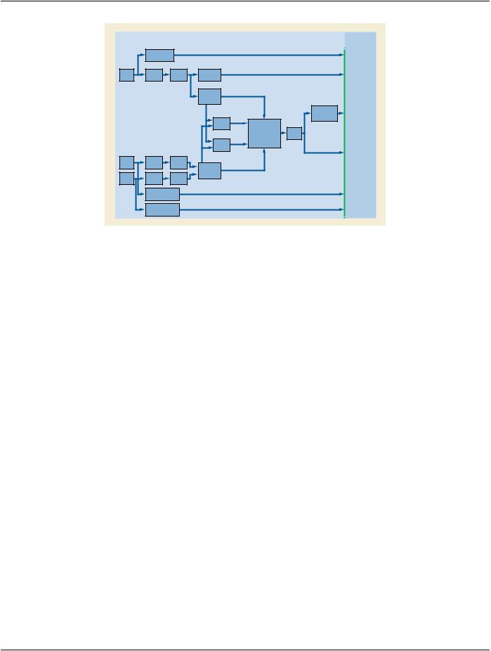
If Data Path Assignment is PRIMARY_SINGLE or SECONDARY_SINGLE, the input to the Palette Color Lookup Table is the number​ of most significant bits specified by Bits Mapped to Color Lookup Table (0028,1403) from the data frame stored pixel values. For Data​ Path Assignment SECONDARY_HIGH or SECONDARY_LOW, the number of most significant bits specified by Bits Mapped to Color​ Lookup Table (0028,1403) from each data frame's stored pixel values are concatenated to create the Palette Color Lookup Table​ input values, with the SECONDARY_HIGH frame's bits comprising the most significant part of the input value and the SECOND-​ ARY_LOW frame's bits comprising the least significant part of the input value.​

If the resulting Palette Color Lookup Table input value is greater than the number of Palette Color Lookup Table entries as specified​ by the Palette Color Lookup Table Descriptor first value, then the output from the Palette Color Lookup Table shall be the last value​ in the Palette Color Lookup Table. However, it is recommended that the values of Bits Mapped To Color Lookup Table (0028,1403)​ and number of Palette Color Lookup Table entries be selected such that all input values are mapped to distinct entries in the Palette​ Color Lookup Table.​

C.7.6.23.4 Blending LUT Transfer Function​

The value of Blending LUT 1 Transfer Function (0028,1405) and Blending LUT 2 Transfer Function (0028,140D) specify the algorithm​ used to determine the output values of the Blending LUT 1 and Blending LUT 2, respectively.​

Enumerated Values:​

CONSTANT​A constant floating point value from 0.0 to 1.0, inclusive​

ALPHA_1​ Pass-through the Alpha 1 input value from the Alpha Palette Color Lookup Table of the Primary data path​ ALPHA_2​ Pass-through the Alpha 2 input value from the Alpha Palette Color Lookup Table of the Secondary data path​ TABLE​ The output of a Table defining a function of the Alphas from both data paths​

ONE_MINUS​The Blending LUT 2 value is (1 - Blending LUT 1 output); used for Blending LUT 2 Transfer Function (0028,140D) only​

If the value is TABLE:​

•​The Alpha 1 input value from the Alpha Palette Color Lookup Table of the Primary data path and the Alpha 2 input value from the​ Alpha Palette Color Lookup Table of the Secondary data are concatenated to form an index into a Lookup Table, with the Alpha 1​ value providing the most significant bits of the index and the Alpha 2 value providing the least significant bits of the index.​

•​If the index is too large for the number of entries in the Lookup Table, the last value of the Lookup Table is used for any index value​ greater than the number of Lookup Table entries. If the index is too small for the number of entries in the Lookup Table, than not​ all entries in the Lookup Table are accessed. The total number of bits in the index value shall be equal to or less than 16.​

C.7.6.23.5 Blending LUT Descriptor​

The three values of the Blending Lookup Table Descriptor (0028,1407) describe the format of the data in Blending Lookup Table Data​ (0028,1408).​

The first value is the number of entries in the lookup table. When the number of table entries is equal to 65,536 (216), then this value​ shall be 0. The number of entries shall be equal to the number of possible values in the input.​

Note​

For example, for 8 bit input to the Blending LUT the tables must have 256 entries, while for 16 bit input to the Blending LUT​ the tables must have 65,536 entries.​

The second value is the first input value mapped, and shall always be 0 for an Blending LUT. This input value is mapped to the first​ entry in the LUT. Subsequent input values are mapped to the subsequent entries in the LUT Data up to an input value equal to​ number of entries + first value mapped - 1 that is mapped to the last entry in the LUT Data. There are no input values greater than​ number of entries - 1.​

The third value specifies the number of bits for each entry in the LUT Data. This value shall be between 8 and 16, inclusive. The LUT​ Data shall be stored in a format equivalent to 16 bits allocated where the high bit is equal to bits stored - 1, where bits stored is the​ third value.​

C.7.6.23.6 Lossy Compression and Palette Color Lookup Tables (Informative)​

Image objects containing non-monotonic Palette Color LUTs that are lossy compressed may potentially experience a change in the​ index values that results in the displayed image having a significantly different appearance than the original image.​

- Standard -​

Page 610​

DICOM PS3.3 2020a - Information Object Definitions​

C.7.6.24 Floating Point Image Pixel Module​

Table C.7.6.24-1 describes the Floating Point Image Pixel Module. This Module differs from the Section C.7.6.3 Image Pixel Module​ in that:​

•​instead of integer stored pixel values, float stored pixel values are used​

•​Bits Stored (0028,0101) and High Bit (0028,0102) are not used because the stored pixel values always occupy the entire word​

•​Pixel Representation (0028,0103) is not used because the stored pixel values are always signed​

•​Photometric Interpretation is constrained​

•​Pixel Data Provider URL (0028,7FE0) is not used​

Table C.7.6.24-1. Floating Point Image Pixel Module Attributes​

Attribute Name​

Tag​

Type​

Attribute Description​

Samples per Pixel​

(0028,0002)​

1​

Number of samples (planes) in this image. See Section C.7.6.3.1.1 for further​


explanation.​

Photometric​

(0028,0004)​

1​

Specifies the intended interpretation of the pixel data.​

Interpretation​


Enumerated Values:​


MONOCHROME2​

Rows​

(0028,0010)​

1​

Number of rows in the image.​

Columns​

(0028,0011)​

1​

Number of columns in the image.​

Bits Allocated​

(0028,0100)​

1​

Number of bits allocated for each pixel sample. Each sample shall have the​


same number of bits allocated. See PS3.5 for further explanation.​


Enumerated Values:​


32​

Float Pixel Data​

(7FE0,0008)​

1​

A data stream of the pixel samples that comprise the Image. The order of​


pixels encoded for each image plane is left to right, top to bottom, i.e., the​


upper left pixel (labeled 1,1) is encoded first followed by the remainder of row​


1, followed by the first pixel of row 2 (labeled 2,1) then the remainder of row​


2 and so on.​

Pixel Aspect Ratio​

(0028,0034)​

1C​

Ratiooftheverticalsizeandhorizontalsizeofthepixelsintheimagespecified​


by a pair of integer values where the first value is the vertical pixel size, and​


thesecondvalueisthehorizontalpixelsize.Requirediftheaspectratiovalues​


do not have a ratio of 1:1 and the physical pixel spacing is not specified by​


Pixel Spacing (0028,0030), or Imager Pixel Spacing (0018,1164) or Nominal​


Scanned Pixel Spacing (0018,2010), either for the entire Image or per-frame​


in a Functional Group Macro. See Section C.7.6.3.1.7.​

Float Pixel Padding​

(0028,0122)​

3​

One limit (inclusive) of a range of pixel values used in an image to pad to​

Value​


rectangular format or to signal background that may be suppressed.​

- Standard -​