Материал: m912201e
WAGO-I/O-PRO 32 V2.2 Overview |
• 39 |
Languages |
|
|
|
2.4.3.10Parallel branch
Two or more branches in SFC can be defined as parallel branches. Each parallel branch must begin and end with a step. Parallel branches can contain alternative branches or other parallel branches. A parallel branch begins with a double line (parallel beginning) and ends with a double line (parallel end) or with a jump. It can be provided with a jump label.
If the parallel beginning line of the previous step is active and the transition condition after this step has the value TRUE, then the first steps of all parallel branches become active (see active step). These branches are now processed parallel to one another. The step after the parallel end line becomes active when all previous steps are active and the transition condition before this step produces the value TRUE.
2.4.3.11Jump
A jump is a connection to the step whose name is indicated under the jump symbol. Jumps are required because it is not allowed to create connections which lead upward or cross each other.
2.4.4 Function Block Diagram (FBD)
The Function Block Diagram is a graphically oriented programming language. It works with a list of networks whereby each network contains a structure which represents either a logical or arithmetic expression, the call of a function block, a jump, or a return instruction.
x Example of a network in the Function Block Diagram
2.4.5 The Continuous Function Chart Editor (CFC)
The continuous function chart editor does not operate like the function block diagram FBD with networks, but rather with freely placeable elements. This allows feedback, for example.
x Example of a network in the continuous function chart editor
WAGO-I/O-SYSTEM 759 WAGO-I/O-PRO 32
40• WAGO-I/O-PRO 32 V2.2 Overview
Languages
2.4.6 Ladder Diagram (LD)
The Ladder Diagram is also a graphics oriented programming language which approaches the structure of an electric circuit.
On the one hand, the Ladder Diagram is suitable for constructing logical switches, on the other hand one can also create networks as in FBD. Therefore the LD is very useful for controlling the call of other POUs.
The Ladder Diagram consists of a series of networks. A network is limited on the left and right sides by a left and right vertical current line. In the middle is a circuit diagram made up of contacts, coils, and connecting lines.
Each network consists on the left side of a series of contacts which pass on from left to right the condition "ON" or "OFF" which correspond to the Boolean values TRUE and FALSE. To each contact belongs a Boolean variable. If this variable is TRUE, then the condition is passed from left to right along the connecting line. Otherwise the right connection receives the value OFF.
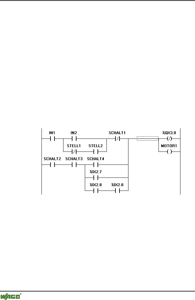
x Example of a network in a Ladder Diagram made up of contacts and coils
2.4.6.1 Contact
Each network in LD consists on the left side of a network of contacts (contacts are represented by two parallel lines: | |) which from left to right show the condition "On" or "Off".
These conditions correspond to the Boolean values TRUE and FALSE. A Boolean variable belongs to each contact. If this variable is TRUE, then the condition is passed on by the connecting line from left to right, otherwise the right connection receives the value "Out".
Contacts can be connected in parallel, then one of the parallel branches must transmit the value "On" so that the parallel branch transmits the value "On"; or the contacts are connected in series, then contacts must transmit the condition "On" so that the last contact transmits the "On" condition. This therefore corresponds to an electric parallel or series circuit.
WAGO-I/O-SYSTEM 759 WAGO-I/O-PRO 32

WAGO-I/O-PRO 32 V2.2 Overview |
• 41 |
Languages |
|
|
|
A contact can also be negated, recognizable by the slash in the contact symbol: |/|. Then the value of the line is transmitted if the variable is FALSE.
2.4.6.2 Coil
On the right side of a network in LD there can be any number of so-called coils which are represented by parentheses:( ). They can only be in parallel. A coil transmits the value of the connections from left to right and copies it in an appropriate Boolean variable. At the entry line the value ON (corresponds to the Boolean variable TRUE) or the value OFF (corresponding to FALSE) can be present.
Contacts and coils can also be negated (in the example the contact SWITCH1 and the coil %QX3.0 is negated). If a coil is negated (recognizable by the slash in the coil symbol: (/)), then it copies the negated value in the appropriate Boolean variable. If a contact is negated, then it connects through only if the appropriate Boolean value is FALSE.
2.4.6.3 Function blocks in the Ladder Diagram
Along with contacts and coils you can also enter function blocks and programs In the network they must have an input and an output with Boolean values and can be used at the same places as contacts, that is on the left side of the LD network
2.4.6.4 Set/Reset coils
Coils can also be defined as set or reset coils. One can recognize a set coil by the "S" in the coil symbol: (S)) It never writes over the value TRUE in the appropriate Boolean variable. That is, if the variable was once set at TRUE, then it remains so.
One can recognize a reset coil by the "R" in the coil symbol: (R)) It never writes over the value FALSE in the appropriate Boolean variable: If the variable has been once set on FALSE, then it remains so.
2.4.6.5 LD as FBD
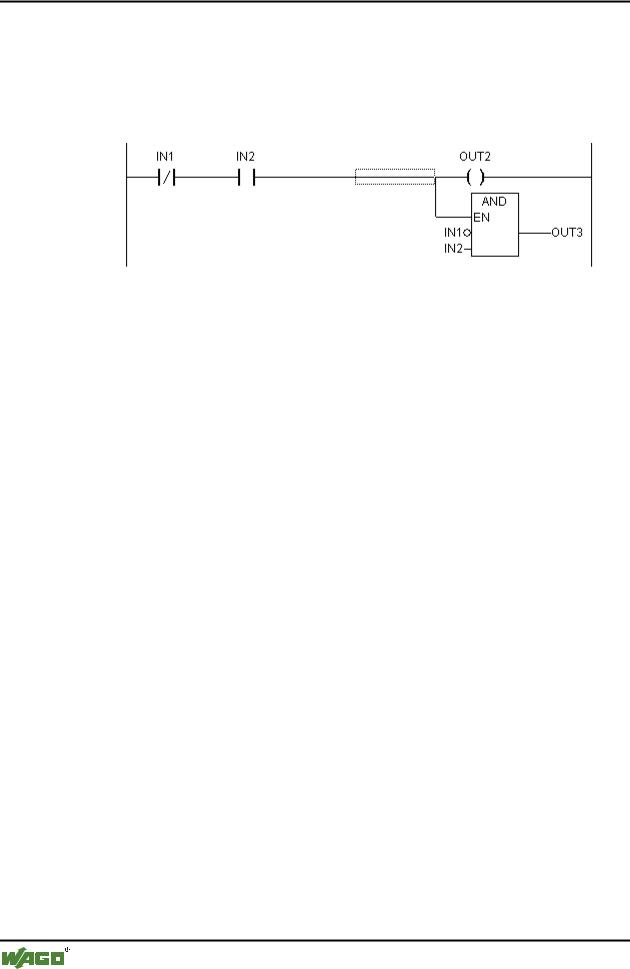
When working with LD it is very possible that you will want to use the result of the contact switch for controlling other POUs. On the one hand you can use the coils to put the result in a global variable which can then be used in another place. You can, however, also insert the possible call directly into your LD network. For this you introduce a POU with EN input.
Such POUs are completely normal operands, functions, programs, or function blocks which have an additional input which is labeled with EN. The EN input is always of the BOOL type and its meaning is: The POU with EN input is evaluated when EN has the value TRUE.
An EN POU is wired parallel to the coils, whereby the EN input is connected to the connecting line between the contacts and the coils. If the ON
WAGO-I/O-SYSTEM 759 WAGO-I/O-PRO 32
42• WAGO-I/O-PRO 32 V2.2 Overview
Debugging, Online Functions
information is transmitted through this line, this POU will be evaluated completely normally.
Starting from such an EN POU, you can create networks similar to FBD.
x Example of a LD network with an EN POU
2.5 Debugging, Online Functions
2.5.1 Sampling Trace
The Sampling Trace allows you to trace the value sequence of variables, depending upon the so-called trigger event. This is the rising edge or falling edge of a previously defined Boolean variable (trigger variable). WAGO-I/O- PRO 32 permits the tracing of up to 20 variables. 500 values can be traced for each variable.
2.5.2 Debugging
The debugging functions of WAGO-I/O-PRO 32 make it easier for you to find errors.
In order to debug, run the command 'Project' 'Options' and in the dialog box that pops up under Build options select activate option Debugging.
2.5.3 Breakpoint
A breakpoint is a place in the program at which the processing is stopped. Thus it is possible to look at the values of variables at specific places within the program.
Breakpoints can be set in all editors. In the text editors breakpoints are set at line numbers, in FBD and LD at network numbers, in CFC at POUs and in SFC at steps. No breakpoints can be set in function block instances.
2.5.4 Single step
Single step means:
In IL: Execute the program until the next CAL, LD or JMP command.
In ST: Execute the next instruction.
In FBD, LD: Execute the next network.
WAGO-I/O-SYSTEM 759 WAGO-I/O-PRO 32

WAGO-I/O-PRO 32 V2.2 Overview |
• 43 |
Debugging, Online Functions |
|
|
|
In SFC: Continue the action until the next step.
By proceeding step by step you can check the logical correctness of your program.
2.5.5 Single Cycle
If Single cycle has been chosen, then the execution is stopped after each cycle.
2.5.6 Change values online
During operations variables can be set once at a certain value (write value) or also described again with a certain value after each cycle (force value). In online mode one also can change the variable value by double click on the value. By that boolean variables change from TRUE to FALSE or the other way round, for each other types of variables one gets the dialog Write Variable xy, where the actual value of the variable can be edited.
2.5.7 Monitoring
In Online mode, all displayable variables are read from the controller and displayed in real time. You will find this display in the declarations and program editor; you can also read out current values of variables in the watch and receipt manager and in a visualization. If variables from instances of function blocks are to be monitored, the corresponding instance must first be opened.
In monitoring VAR_IN_OUT variables, the de-referenced value is output.
In monitoring pointers, both the pointer and the de-referenced value are output in the declaration portion. In the program portion, only the pointer is output:
+ --pointervar = '<'pointervalue'>'
POINTERs in the de-referenced value are also displayed accordingly. With a simple click on the cross or a double-click on the line, the display is either expanded or truncated.
x Example for Monitoring of Pointers
WAGO-I/O-SYSTEM 759 WAGO-I/O-PRO 32