Материал: m912201e
Programming Example • 49
Controlling a Traffic Signal Unit
In order to insert an operator in front of another operator, you must select the place where the input to which you want to attach the operator feeds into the box.
Then use the command 'Insert' 'Box'. Otherwise you can set up these networks in the same way as the first network.
Now our first POU has been finished. TRAFFICSIGNAL, according to the input of the value STATUS, controls whichever light color we wish.
3.1.8 Connecting the standard.lib
For the timer in the POU WAIT we need a POU from the standard library. Therefore, open the library manager with 'Window' 'Library Manager. Choose 'Insert' 'Additional library'. The dialog box appears for opening files. From the list of the libraries choose standard.lib.
WAGO-I/O-SYSTEM 759 WAGO-I/O-PRO 32
50 • Programming Example
Controlling a Traffic Signal Unit
3.1.9 "WAIT" declaration
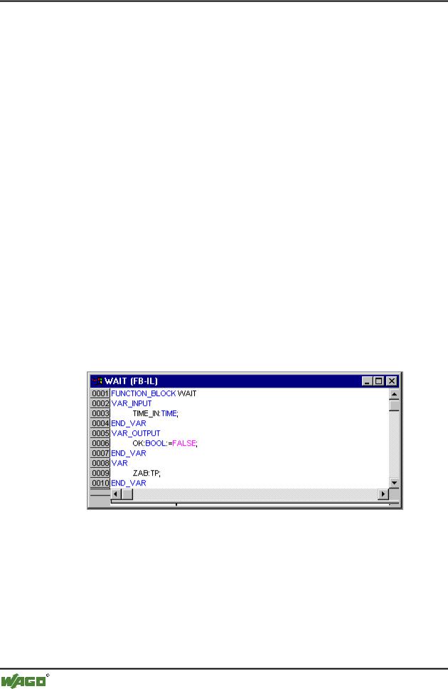
Now let us turn to the POU WAIT. This POU is supposed to become a timer with which we can determine the length of the time period of each TRAFFICSIGNAL phase. Our POU receives as input variable a variable TIME of the type TIME, and as output it produces a Boolean value which we want to call OK and which should be TRUE when the desired time period is finished. We set this value with FALSE by inserting at the end of the declaration (before the semicolon, however) " := FALSE ".
For our purposes we need the POU TP, a clock generator. This has two inputs (IN, PT) and two outputs (Q, ET). TP does the following:
As long as IN is FALSE, ET is 0 and Q is FALSE. As soon as IN provides the value TRUE, the time is calculated at the output ET in milliseconds. When ET reaches the value PT, then ET is no longer counted. Meanwhile Q produces TRUE as long as ET is smaller than PT. As soon as the value PT has been reached, then Q produces FALSE again. In addition you will find a short description of all POUs from the standard library in the appendix.
In order to use the POU TP in the POU WAIT we must create a local instance from TP. For this we declare a local variable ZAB (for elapsed time) of the type TP (between the keywords VAR, END_VAR).
The declaration part of WAIT thus looks like this:
x Function Block WAIT, Declaration Part
3.1.10"WAIT" body
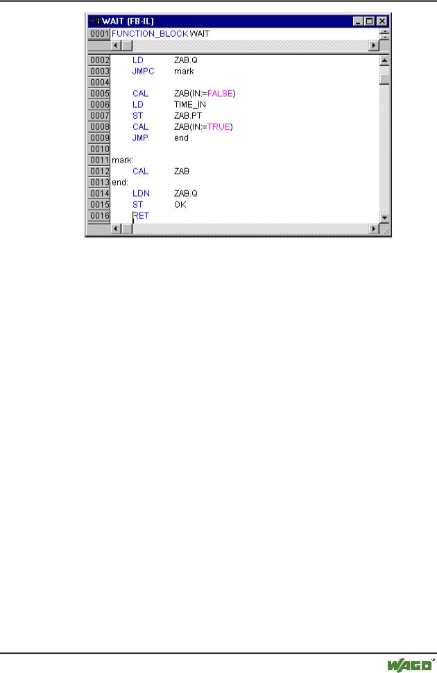
In order to create the desired timer, the body of the POU must be programmed as follows:
x Function Block WAIT, Instruction Part
WAGO-I/O-SYSTEM 759 WAGO-I/O-PRO 32
Programming Example • 51
Controlling a Traffic Signal Unit
At first it is checked whether Q has already been set at TRUE (as though the counting had already been executed), in this case we change nothing with the occupation of ZAB, but we call the function block ZAB without input (in order to check whether the time period is already over).
Otherwise we set the variable IN in ZAB at FALSE, and therefore at the same time ET at 0 and Q at FALSE. In this way all variables are set at the desired initial condition. Now we assign the necessary time from the variable TIME into the variable PT, and call ZAB with IN:=TRUE. In the function block ZAB the variable ET is now calculated until it reaches the value TIME, then Q is set at FALSE.
The negated value of Q is saved in OK after each execution of WAIT. As soon as Q is FALSE, then OK produces TRUE.
The timer is finished at this point. Now it is time to combine our two function blocks WAIT and TRAFFICSIGNAL in the main program PLC_PRG.
3.1.11"SEQUENCE" first expansion level
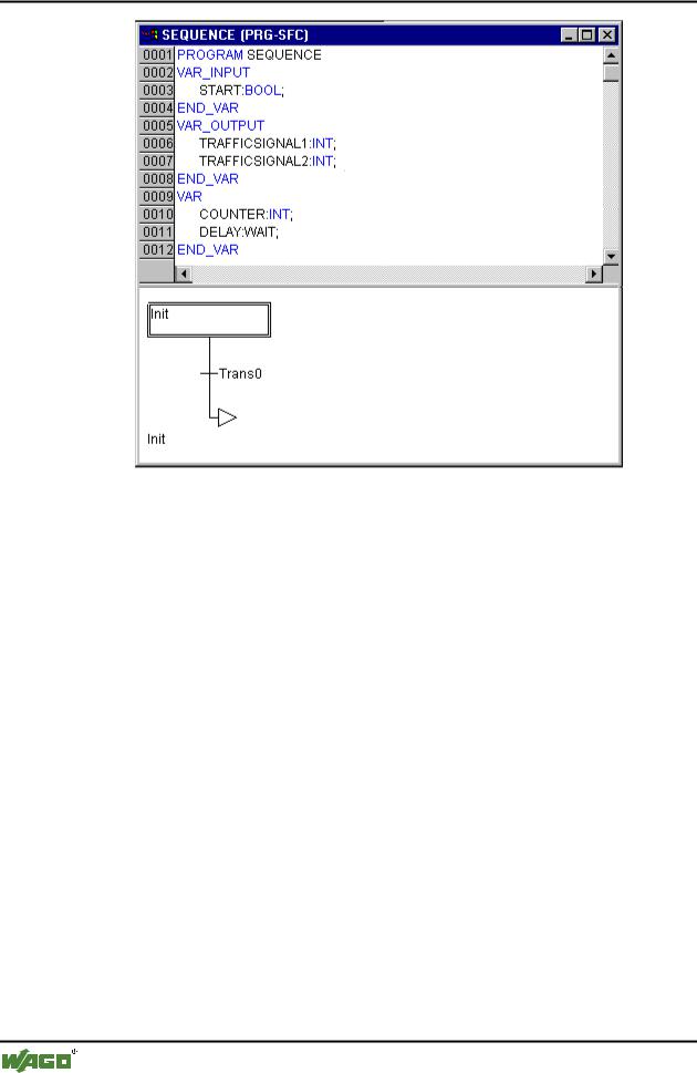
First we declare the variables we need. They are: an input variable START of the type BOOL, two output variables TRAFFICSIGNAL1 and TRAFFICSIGNAL2 of the type INT and one of the type WAIT (DELAY as delay). The program SEQUENCE now looks like shown here:
x Program Sequence, First Expansion Level, Declaration Part
WAGO-I/O-SYSTEM 759 WAGO-I/O-PRO 32
52 • Programming Example
Controlling a Traffic Signal Unit
3.1.12Create a SFC diagram
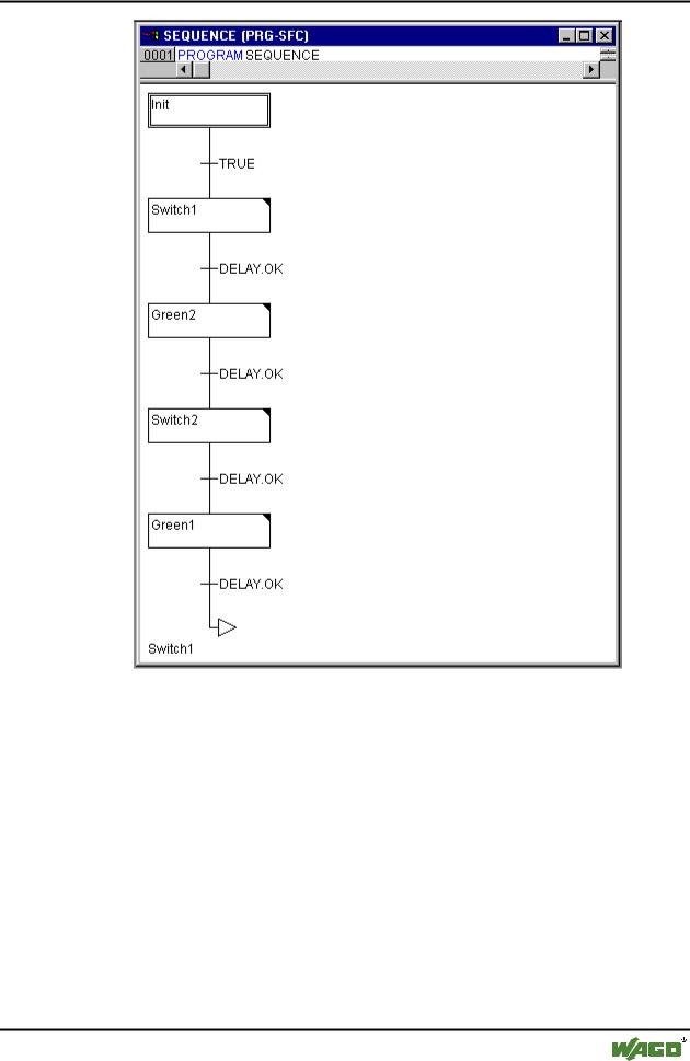
The beginning diagram of a POU in SFC always consists of an action "Init" of a following transition "Trans0" and a jump back to Init. We have to expand that.
Before we program the individual action and transitions let us first determine the structure of the diagrams. We need one step for each TRAFFICSIGNAL phase. Insert it by marking Trans0 and choosing 'Insert' 'Step transition (after)'. Repeat this procedure three more times.
If you click directly on the name of a transition or a step, then this is marked and you can change it. Name the first transition after Init "START", and all other transitions "DELAY.OK".
The first transition switches through when START is TRUE and all others switch through when DELAY in OK produces TRUE, i.e. when the set time period is finished.
The steps (from top to bottom) receive the names Switch1, Green2, Switch2, Green1, whereby Init of course keeps its Name. "Switch" should include a yellow phase, at Green1 TRAFFICSIGNAL1 will be green, at Green2 TRAFFICSIGNAL2 will be green. Finally change the return address of Init after Switch1. If you have done everything right, then the diagram should look like in the following image:
x Program SEQUENCE, First Expansion Level, Instruction Part
WAGO-I/O-SYSTEM 759 WAGO-I/O-PRO 32
Programming Example • 53
Controlling a Traffic Signal Unit
Now we have to finish the programming of the individual steps. If you doubleclick on the field of a step, then you get a dialog for opening a new action. In our case we will use IL (Instruction List).
3.1.13Actions and transition conditions
In the action of the step Init the variables are initialized, the STATUS of TRAFFICSIGNAL1 should be 1 (green). The state of TRAFFICSIGNAL2 should be 3 (red). The action Init then looks like in the following image:
x Action Init
WAGO-I/O-SYSTEM 759 WAGO-I/O-PRO 32