Материал: m013807e
Technical Data
Item number 750-
Number of inor outputs
Nominal voltage
Internal current consumption
Voltage (field side)
Current via power jumper contacts
Input current (field side)
Isolation
Internal bit width
Configuration
Operating temperature
Wire connection
Dimensions (mm) WxHxL
622
2, 4, 6 or 8
5 V DC internal
10 mA max.
24 V DC (-15%/+20%)
10 A max.
-
500 V system/power supply
2, 4, 6 oder 8
none, optional via software parameter
0°C....+55°C
CAGE CLAMP; 0.08 to 2.5mm2
12 x 64* x 100 (*from upper edge of the carrier rail)
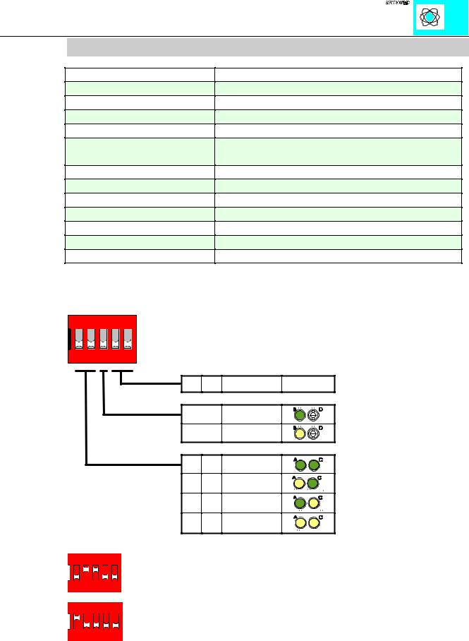
The DIP switches and LEDs are used as follows. When the switch is OFF the LED is also OFF (dark green symbol). When the switch is ON the LED lightens (yellow symbol).
ON
1 2 3 4 5
;;
2))
21
2)) 2)) 21 2)) 2)) 21 21 21
'RQ·W FDUH
,QSXWV
2XWSXWV
%LW [ %LW
%LW [ %LW
%LW [ %LW
%LW [ %LW
Examples:
|
|
ON |
|
|||||||||||||||||
|
|
|
|
|
|
|
|
|
|
|
|
|
|
|
|
|
|
|
|
|
1 |
2 |
3 |
4 |
5 |
6 binary outputs (3x 2-channel output modules) |
|||||||||||||||
|
|
|
|
|
|
|
|
|
||||||||||||
|
|
|
|
|
|
|
|
|
|
|
|
|
|
|
|
|
|
|
||
|
|
|
|
|
|
|
|
|
|
|
|
|
|
|||||||
|
|
|
ON |
|
||||||||||||||||
|
|
|
|
|
|
|
|
|
|
|
|
|
||||||||
|
1 |
2 |
3 |
4 |
5 |
4 binary inputs (2x 2-channel input modules) |
||||||||||||||
|
|
|
|
|
|
|
|
|
|
|
|
|||||||||
Binary spacer module 750-622 |
2 |
|
:$*2 , 2 6<67(0 |