Материал: m013203e
Organization of the inand output data:
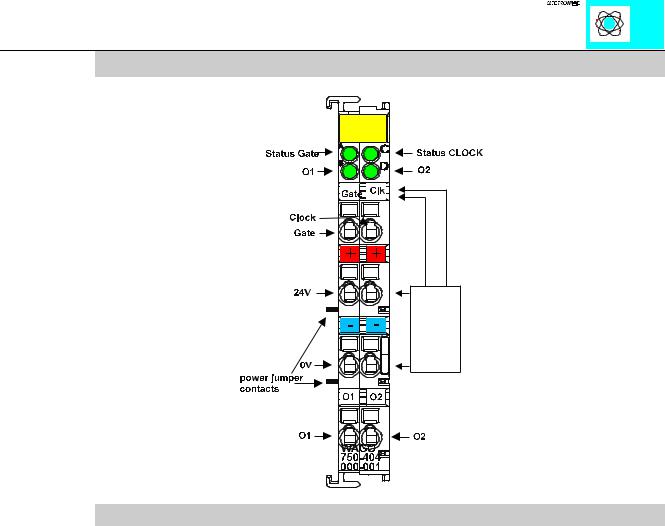
The counter begins processing with pulses at the CLOCK input. The changes from 0 V to 24 V are counted.
The counter counts up, if the input U/D is set at 24 V. With an open circuit input or 0 V the counter counts backwards.
The two bottom contacts each include another output. These outputs are activated through bits in the control byte.
The control byte has the following bits:
Control Byte
Bit 7 |
Bit 6 |
Bit 5 |
Bit 4 |
Bit 3 |
Bit 2 |
Bit 1 |
Bit 0 |
|
|
|
|
|
|
|
|
0 |
x |
Set Counter |
Block Counter |
Output value at |
Output value at |
x |
x |
|
|
|
|
output O2 |
output O1 |
|
|
|
|
|
|
|
|
|
|
The status byte has the following bits:
Status Byte
Bit 7 |
Bit 6 |
Bit 5 |
Bit 4 |
Bit 3 |
Bit 2 |
Bit 1 |
Bit 0 |
|
|
|
|
|
|
|
|
x |
x |
Counter is |
Counter is |
actual signal at |
actual signal |
actual signal at |
actual signal at |
|
|
set |
blocked |
O2 |
at O1 |
input U/D |
input CLOCK |
|
|
|
|
|
|
|
|
With the control and status-byte the following tasks are possible:
Set the counter: Put Bit 5 into the control byte. The counter with the 32 bit value is loaded into output bytes 0-3. As long as the bits are set, the counter can stop and information is stored. The ensuing data of the counter will be conveyed to the status byte.
Blocking the counter: Bit 4 is set into the control byte, then the count process is suppressed. Bit 4 in the status byte communicates the suppression of the counter.
Set the outputs: Bits 2 and 3 set the additional two outputs of the counter module.
The result of the counter is in binary.
Counter Module 750-404 |
3 |
|
:$*2 , 2 6<67(0 |
An example:
The counter is set with “Set Counter” to the value 0x0000.0000
- 0X1X.XXXX, 0x00, 0x00, 0x00, 0x00 are carried over as output value (carry over the control-byte and the new counter position),
-wait until the input value is 0X1X.XXXX, 0x00, 0x00, 0x00, 0x00 (the status-byte shows the loading feedback) ,
-carry over 0x00, 0x00, 0x00, 0x00, 0x00 as output value (release counter).
Wait for the first and further counting pulse |
|
-the input value is XX00.XXXX, 0x00, 0x00, 0x00, 0x00 |
(no counting pulse received) |
-the input value is XX00.XXXX, 0x00, 0x00, 0x00, 0x01 |
(1 counting pulse received) |
-the input value is XX00.XXXX, 0x00, 0x00, 0x00, 0x02 |
(2 counting pulses received) |
-.................
-the input value is XX00.XXXX, 0xFF, 0xFF, 0xFF, 0xFF (maximum counting position is reached)
-the input value is XX00.XXXX, 0x00, 0x00, 0x00, 0x00 (a further counting pulse causes an overflow)
-the input value is XX00.XXXX, 0x00, 0x00, 0x00 0x01, (a further counting pulse is received)
Notes: 0x23 is a value in hexadecimal form 0101.1001 is a value in binary form
“X” is used if the value at this position is without any significance.
Counter Module 750-404 |
4 |
|
:$*2 , 2 6<67(0 |
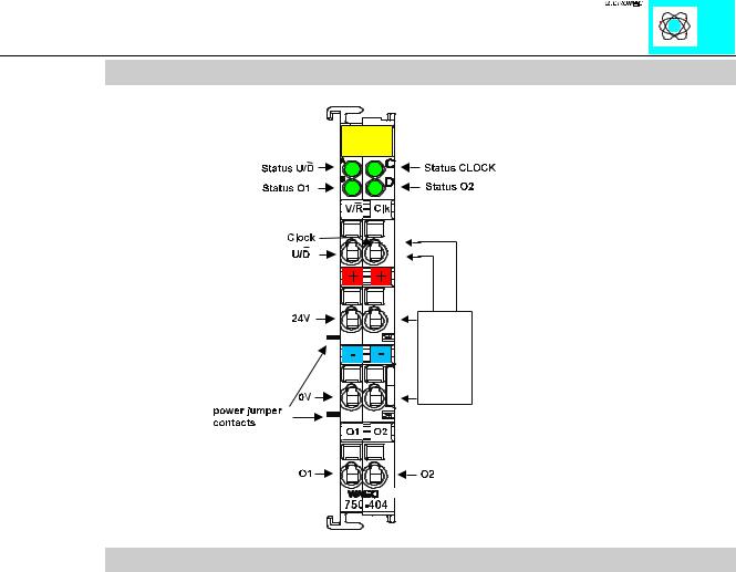
Counter with enable input 750-404/000-001
Technical description:
The counter module also can be ordered as counter with enable input (750-404/000- 001).
The counter begins processing with pulses at the CLOCK input. The changes from 0 V to 24 V are counted.
The counter counts down if the input U/D is set at 24 V. With an open circuit input or 0 V the counter counts up.
The data format of the module is 4 bytes data and a control/status byte. The module is a 32 Bit counter. The ID Code os 180 (0xB4). The format of input and output data is the same as 750-404.
The counter module is able to run with all WAGOÇI/OÇSYSTEM bus-couplers (except for the economy type).
Counter Module 750-404 |
5 |
|
:$*2 , 2 6<67(0 |
Peak Time Counter 750-404/000-002
Technical data
The counter module also can be ordered as peak time counter with 750-404/000-002.
This description is only intended for hardware version X X X X 0 0 0 1- - - -. The serial number can be found on the right side of the module.
The counter begins processing with pulses at the CLOCK input. The changes from 0 V to 24 V are counted.
The counter counts up if the input U/D is set at 24 V. With an open circuit input or 0 V the counter counts backwards.
The two bottom contacts each include another output. These outputs are activated through bits in the control byte.
The counter module is able to run with all WAGOÇI/OÇSYSTEM bus-couplers (except for the economy type).
Counter Module 750-404 |
6 |
|
:$*2 , 2 6<67(0 |
Organization of the inand output data:
The counter begins processing with pulses at the CLOCK input for a special time span. The time span is predefined as 10 s. The state of the counter is stored in the processs image until the next period. After the recording the counting starts again at 0.
The activation of the counting and the synchronisation with the SPS is made by a handshake in the control and status byte.
The end of thre counting period and thus the new process data is signaled by a toggel bit in the status byte.
The control byte has the following bits:
Control Byte
Bit 7 |
Bit 6 |
Bit 5 |
Bit 4 |
Bit 3 |
Bit 2 |
Bit 1 |
Bit 0 |
|
|
|
|
|
|
|
|
0 |
0 |
start of the |
0 |
Output value at |
Output value at |
0 |
0 |
|
|
periodic |
|
output O2 |
output O1 |
|
|
|
|
counting |
|
|
|
|
|
|
|
|
|
|
|
|
|
The status byte has the following bits:
Status Byte
Bit 7 |
Bit 6 |
Bit 5 |
Bit 4 |
Bit 3 |
Bit 2 |
Bit 1 |
Bit 0 |
|
|
|
|
|
|
|
|
0 |
0 |
counting |
0 |
actual signal at |
actual signal |
actual signal at |
Toggelbit for |
|
|
started |
|
O2 |
at O1 |
input U/D |
end of the |
|
|
|
|
|
|
|
record |
|
|
|
|
|
|
|
|
Counter Module 750-404 |
7 |
|
:$*2 , 2 6<67(0 |