Материал: m013203e
Digital Inputs (24 V AC/DC, 120 V AC, 230 V AC, 48 V DC) PN: 750-400...415
Technical description
The supply is applied by a series-connected termination to each I/O module for the respective operating voltage. Power connections are made automatically from module to module when snapped onto the DIN rail.
Attention:
The lowest power jumper contact is not carried out for some modules (e.g. 4-channel)! A module which needs all contacts (e.g. 2 channel digital) may not be connected to the right hand side of modules which do not have 3 power jumper contacts (e.g. 4 channel modules).
All 2-channel digital inputs are 4-conductor devices allowing the direct connection of 4- conductor sensors with the terminations V+, 0V, ground and signal.
The 4-channel digital inputs are suitable for the direct connection of two 3-conductor sensors (V+, 0V, signal). The power distribution module 750-614 is available for the connection of more sensors to V+ and 0V.
The modules 750-408 and 750-409 are low-side switching.
A 2-wire proximity switch can be connected to the modules 750-410 and 750-411. RC filters are series-connected to the 5, 24 and 48 V versions for noise rejection and switch debouncing. They are available with time constants of 3.0 ms and 0.2 ms.
The standard numerical assignment for bus operations is from left to right, starting with the LSB. The positions of the different I/O modules in the configured node/station are selectable by the user. A block type configuration is not necessary.
The Input module can be connected to all buscouplers of the WAGOÇI/OÇSYSTEM.
Digital Inputs 750-400...415 |
1 |
:$*2Ç, 2Ç6<67(0

Technical Data:
Item Number 750-
Number of inputs
Input filter
Nominal voltage
Signal voltage (0)
Signal voltage (1)
Input current (internal)
Input current (field side)
Isolation
Internal bit width
Configuration
Operating temperature
Wire connection
Dimensions (mm) WxHxL
Item Number 750-
Number of inputs
Input filter
Nominal voltage
Signal voltage (0)
Signal voltage (1)
Input current (internal)
Input current (field side)
Isolation
Internal bit width
Configuration
Operating temperature
Wire connection
Dimensions (mm)WxHxL
400 |
|
401 |
|
402 |
|
403 |
|
2 |
|
|
4 |
||
3 ms |
|
0.2 ms |
|
3 ms |
|
0.2 ms |
|
|
24V DC (-15%/+20%) |
|
|
||
-3V...+5V DC (std. EN 61131 Typ 1) |
||||||
15V...30V DC (std. EN 61131 Typ 1) |
||||||
2.5 mA max. |
|
5 mA max. |
||||
|
|
5 mA typ. |
|
|
|
|
|
500 V system/power supply |
|
|
|||
|
2 |
|
|
|
4 |
|
no address or configutation adjustment
0°C....+55°C
CAGE CLAMP; 0.08 to 2.5mm2
12 x 64* x 100 (*from upper edge of carrier rail)
|
405 |
406 |
|
410* |
|
|
411* |
|
|
|
2 |
|
|
|
|
2 |
|
||
|
10 ms |
|
3 ms |
|
|
0.2 ms |
|
||
|
|
|
|
|
|
|
|
|
|
|
230 V AC |
|
120 V AC |
|
24V DC (-15%/+20%)) |
|
|||
|
(-15%/+10%) |
|
(- |
|
|
|
|
|
|
|
|
|
15%/+10%) |
|
|
|
|
|
|
|
0 V...40 V |
|
0 V..20 V |
|
-3 V ... +5 V DC (std. |
|
|||
|
AC |
|
AC |
|
EN 61131 Type 2) |
|
|||
|
79 V...1.1 UN |
|
79 V...1.1 |
|
11 V ... 30 V DC (std. |
|
|||
|
AC |
|
UN AC |
|
EN 61131 Type 2) |
|
|||
|
2 mA |
|
2.5 mA max. |
|
|||||
|
6.5 mA typ. |
|
4.5 mA typ. |
|
8 mA typ. |
|
|||
|
4 kV system/power supply |
|
500 V system/power |
|
|||||
|
|
|
|
|
|
supply |
|
||
|
|
2 |
|
|
|
|
|
|
|
|
no address or configuration adjustment |
|
|||||||
|
|
|
0°C....+55°C |
|
|
|
|
||
CAGE CLAMP; 0.08 to 2.5mm2
12 x 64* x 100 (*from upper edge of the carrier rail)
*) 2 - wire proximity switch, current without load max. 2 mA
Digital Inputs 750-400...415 |
2 |
:$*2Ç, 2Ç6<67(0
Item Number 750-
Number of inputs
Input filter
Nominal voltage
Signal voltage (0)
Signal voltage (1)
Input current (internal)
Input current (field side)
Isolation
Internal bit width
Configuration
Operating temperature
Wire connection
Dimensions (mm)WxHxL
408 |
|
409 |
|
4 |
|
3 ms |
|
0,2 ms |
24V DC (-15% / +20%) |
||
15 V...30 V DC |
||
-3 |
V...5 |
V DC |
10 mA max.
|
|
|
|
|
|
|
|
|
|
|
|
|
|
|
|
|
|
|
|
|
|
|
|
412 |
|
413 |
|
|
|
|
2 |
|
|
|
|
3 ms |
|
|
0,2 ms |
|
|
48 V DC (-15% / +20%)
-6 V ... +10 V DC
34 V ... 60 V DC
5 mA max.
3.5 mA typ.
500 V system/power supply
4 |
2 |
no address or configuration adjustment
0°C....+55°C
CAGE CLAMP; 0,08 to 2,5 mm2
12 x 64* x 100 (*from upper edge of the carrier rail)
Item Number 750-
Number of inputs
Input filter /
Conversion time
Nominal voltage
Signal voltage (0)
Signal voltage (1)
Input current (internal)
Input current (field side)
Isolation
Internal bit width
Configuration
Operating temperature
Wire connection
Dimensions (mm)WxHxL
414 |
415 |
4 |
4 |
0.2 ms |
20 ms |
|
|
5 V DC |
24 V AC/DC |
|
(-15%/+20%) |
0...0.8 V DC |
-3...+5 V DC |
|
0...+5 V AC |
2.4 V...5 V DC |
11 ... 30 V DC |
|
10 ... 27 V AC |
5 mA |
10 mA |
50 µA typ. |
7.5 mA DC |
|
7.6 9.5 mA AC |
500 V system/power supply |
500V system/power |
|
supply |
|
50 V channel/channel |
4 |
4 |
no address or configuration adjustment
0°C....+55°C
CAGE CLAMP; 0,08 to 2,5 mm2
12 x 64* x 100 (*from upper edge of the carrier rail)
Digital Inputs 750-400...415 |
3 |
:$*2Ç, 2Ç6<67(0
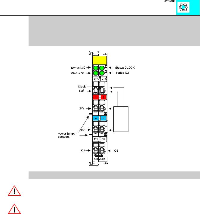
Counter modules
PN 750-404, 750-404/000-001, 750-404/000-002 750-404/000-003, 750-404/000-004
Up/Down Counter 100 kHz, 750-404
Technical Description:
Attention! The description that is in the I/O ring binder data pages (88-530/013-600 dated 7/96) is not correct. The bottom contacts are additional outputs.
Attention:
The lowest power jumper contact is not carried out for some modules (e.g. 4-channel)! A module which needs all contacts (e.g. 2 channel digital) may not be connected to the right hand side of modules which do not have 3 power jumper contacts (e.g. 4 channel modules).
The described configuration is counter with up/down input.
The following description is preliminary and is applicable to the factory configuration.
The counter module is able to run with all WAGOÇI/OÇSYSTEM bus-couplers (except for the economy type).
Counter Module 750-404 |
1 |
|
:$*2 , 2 6<67(0 |
Technical Data:
Item Number: 750-
Number of outputs
Output current
Number of counter
Input current (internal)
Nominal voltage
Signal voltage (0)
Signal voltage (1)
Switching rate
Output current
Counter size
Isolation
Bit width
Configuration
Operating temperature
Wire connection
Size (mm)WxHxD
|
|
|
|
|
|
|
|
|
|
|
|
|
|
|
|
|
|
|
|
|
|
|
|
|
|
|
|
|
|
|
|
404, 404/000-001 |
|
404/000-002 |
|
|
|||
404/000-004 |
|
|
|
|
|
|
|
2 |
|
|
|
|
|
|
|
0.5 A |
|
|
|
|
|
|
|
1 |
|
|
|
|
|
|
|
70 mA |
|
|
|
|
|
|
|
24 V DC (-15% +20%) |
|
||||||
-3V.....+5V DC |
|
|
|
|
|
|
|
+15V...+30V DC |
|
||||||
100 kHz |
|
10 kHz max. |
|
||||
5 mA typ.
32 Bit
500 V system/power supply
32 Bit (8 Bit verification; 8 bit not used)
none, optional with software parameter
0°C....+55°C
CAGE CLAMP; 0.08 to 2.5mm2
12 x 64* x 100 (*from upper edge of the carrier rail)
Counter Module 750-404 |
2 |
|
:$*2 , 2 6<67(0 |