Материал: m012900e

Внимание! Если размещение файла нарушает Ваши авторские права, то обязательно сообщите нам

302 • Application examples

7 Application examples

7.1 Test of MODBUS protocol and fieldbus nodes

i

i

You require a MODBUS master to test the function of your fieldbus node. For this purpose, various manufacturers offer a range of PC applications that you can, in part, download from the Internet as free of charge demo versions.

One of the programs which is particularly suitable to test your ETHERNET TCP/IP fieldbus node, is for instance ModScan from Win-Tech.

More information

A free of charge demo version from ModScan32 and further utilities from Win-Tech can be found in the Internet under: http://www.win-tech.com/html/demos.htm.

ModScan32 is a Windows application that works as a MODBUS master. This program allows you to access the data points of your connected ETHERNET TCP/IP fieldbus node and to proceed with the desired changes.

More information

For a description example relating to the software operation, please refer to:

http://www.win-tech.com/html/modscan32.htm

7.2 Visualization and control using SCADA software

This chapter is intended to give insight into how the WAGO ETHERNET fieldbus coupler/controller can be used for process visualization and control using standard user software.

There is a wide range of process visualization programs, called SCADA Software, from various manufacturers.

More information

i For a selection of SCADA products, look under i.e.: http://www.abpubs.demon.co.uk/scadasites.htm.

SCADA is the abbreviation for Supervisory Control and Data Acquisition.

It is a user-orientated tool used as a production information system in the areas of automation technology, process control and production monitoring.

The use of SCADA systems includes the areas of visualization and monitoring, data access, trend recording, event and alarm processing, process analysis and targeted intervention in a process (control).

The WAGO ETHERNET fieldbus node provides the required process input and output values.

Modular I/O System

ETHERNET TCP/IP

Application examples 303

Attention!

When choosing suitable SCADA software, ensure that it provides a MODBUS device driver and supports the MODBUS/TCP functions in the coupler.

Visualization programs with MODBUS device drivers are available from i.e. Wonderware, National Instruments, Think&Do or KEPware Inc., some of which are available on the Internet as demo versions.

The operation of these programs is very specific.

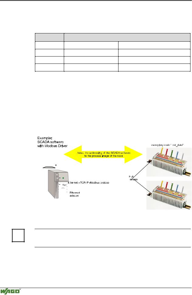
However, a few essential steps are described to illustrate the way an application can be developed using a WAGO ETHERNET fieldbus node and SCADA software in principle.

The initial prerequisite is that the MODBUS ETHERNET driver has been loaded and MODBUS ETHERNET has been selected.

Subsequently, the user is requested to enter the IP address for addressing the fieldbus node.

At this point, some programs allow the user to give the node an alias name, i.e. to call the node "Measuring data". The node can then be addressed with this name.

Then, a graphic object can be created, such as a switch (digital) or a potentiometer (analog).

This object is displayed on the work area and is linked to the desired data point on the node.

This link is created by entering the node address (IP address or alias name) of the desired MODBUS function codes (register/bit read/write) and the MODBUS address of the selected channel.

Entry is, of course, program specific.

Depending on the user software the MODBUS addressing of a bus module can be represented with 3 or, as in the following example, with 5 digits.

Modular I/O System

ETHERNET TCP/IP

304 • Application examples

Example of the MODBUS function code

In the case of SCADA Software Lookout from National Instruments the MODBUS function codes are used with a 6 bit coding, whereby the first bit represents the function code:

Input code: MODBUS function code

0FC1 ¬ read coils

1FC2 ¬ read input discretes

3FC3 ¬ read multiple registers

4FC4 ¬ read input registers

Reading of several input bits

Reading of several input bits

Reading of several input registers

Reading of an individual input register

The following five digits specify the channel number of the consecutively numbered digital or analog input and/or output channels.

Examples:


-

Read the first digital input:

i.e. 0 0000 1

-

Read the second analog input:

i.e. 3 0000 2

Application example:

Thus, the digital input channel 2 of the above node "Measuring data" can be read out with the input: "Measuring data. 0 0000 2".


Fig. 7-1: Example of user software


G012913e

More information

i Please refer to the respective SCADA product manual for a detailed description of the particular software operation.

Modular I/O System

ETHERNET TCP/IP

Application in Explosive Environments 305

8 Application in Explosive Environments

8.1 Foreword

Today’s development shows that many chemical and petrochemical companies have production plants, production, and process automation machines in operation which use gas-air, vapor-air and dust-air mixtures which can be explosive. For this reason, the electrical components used in such plants and systems must not pose a risk of explosion resulting in injury to persons or damage to property. This is backed by law, directives or regulations, on a national and international scale. WAGO-I/O-SYSTEM 750 (electrical components) is designed for use in zone 2 explosive environments. The following basic explosion protection related terms have been defined.

8.2 Protective measures

Primarily, explosion protection describes how to prevent the formation of an explosive atmosphere. For instance by avoiding the use of combustible liquids, reducing the concentration levels, ventilation measures, to name but a few. But there are a large number of applications, which do not allow the implementation of primary protection measures. In such cases, the secondary explosion protection comes into play. Following is a detailed description of such secondary measures.

8.3 Classification meeting CENELEC and IEC

The specifications outlined here are valid for use in Europe and are based on the following standards: EN50... of CENELEC (European Committee for Electrotechnical Standardisation). On an international scale, these are reflected by the IEC 60079-... standards of the IEC (International Electrotechnical Commission).

8.3.1Divisions

Explosive environments are areas in which the atmosphere can potentially become explosive. The term explosive means a special mixture of ignitable substances existing in the form of air-borne gases, fumes, mist or dust under atmospheric conditions which, when heated beyond a tolerable temperature or subjected to an electric arc or sparks, can produce explosions. Explosive zones have been created to describe the concentrations level of an explosive atmosphere. This division based on the probability of an explosion occurring is of great importance both for technical safety and feasibility reasons, knowing that the demands placed on electrical components permanently employed in an explosive environment have to be much more stringent than those placed on electrical components that are only rarely and, if at all, for short periods, subject to a dangerous explosive environment.

Modular I/O System

ETHERNET TCP/IP

306 • Application in Explosive Environments

Explosive areas resulting from gases, fumes or mist:

Zone 0 areas are subject to an explosive atmosphere (> 1000 h /year) continuously or for extended periods.

Zone 1 areas can expect the occasional occurrence of an explosive atmos-

phere (> 10 h 1000 h /year).

Zone 2 areas can expect the rare or short-term occurrence of an explosive atmosphere (> 0 h 10 h /year).

Explosive areas subject to air-borne dust:

Zone 20 areas are subject to an explosive atmosphere (> 1000 h /year) continuously or for extended periods.

Zone 21 areas can expect the occasional occurrence of an explosive atmos-

phere (> 10 h 1000 h /year).

Zone 22 areas can expect the rare or short-term occurrence of an explosive atmosphere (> 0 h 10 h /year).

8.3.2Explosion protection group

In addition, the electrical components for explosive areas are subdivided into two groups:

Group I: Group I includes electrical components for use in fire-damp endangered mine structures.

Group II: Group II includes electrical components for use in all other explosive environments. The group is further subdivided by pertinent combustible gases in the environment.

Subdivision IIA, IIB and IIC takes into account that different materials/substances/gases have various ignition energy characteristic values. For this reason the three sub-groups are assigned representative types of gases:

IIA – Propane

IIB – Ethylene

IIC – Hydrogen

Minimal ignition energy of representative types of gases

Explosion group

I

IIA

IIB

IIC


Gases

Methane

Propane

Ethylene

Hydrogen


Ignition energy (µJ)

280

250

82

16


Hydrogen being commonly encountered in chemical plants, frequently the explosion group IIC is requested for maximum safety.

Modular I/O System

ETHERNET TCP/IP