Материал: hcf4017b
HCF4017B
TYPICAL APPLICATIONS
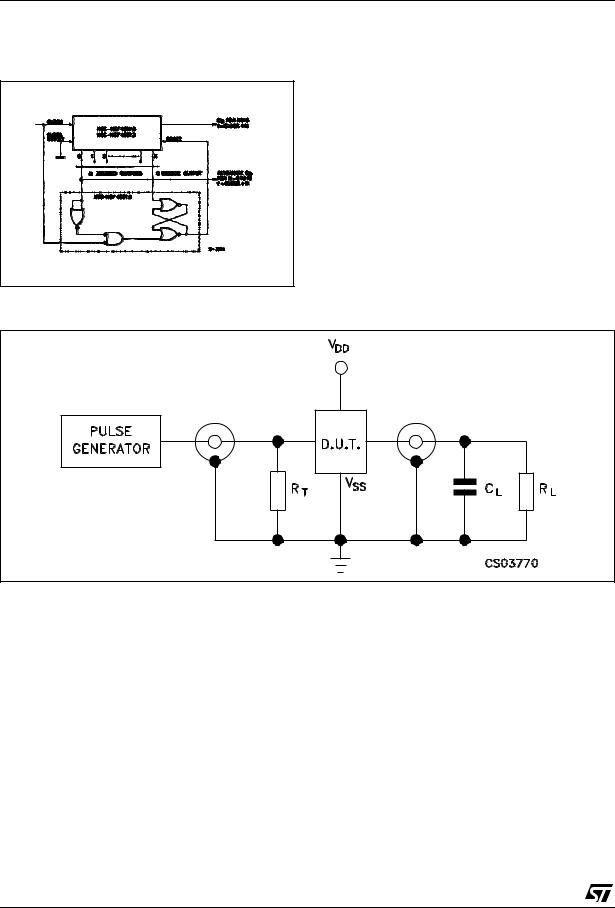
DIVIDE BY N COUNTER(N < 10) WITH DECODED OUTPUTS
When the Nth decoded output is reached (Nth clock pulse) the S-R flip-flop (constructed from two NOR gates of the HCF4001B) generates a reset pulse which clears the HCF4017B to its zero count. At this time, if the Nth decoded output is greater than or equal to 6, the COUT line goes high to clock the next HCF4017B counter section. The "0" decoded output also goes high at this time. Coincidence of the clock low and decoded "0" output high resets the S-R flip-flop to enable the HCF4017B. If the Nth decoded output is less than 6, the COUT line will not go high and, therefore, cannot be used. In this case "0" decoded output may be used to perform the clocking function for the next counter.
TEST CIRCUIT
CL = 50pF or equivalent (includes jig and probe capacitance) |
RL = 200KΩ |
RT = ZOUT of pulse generator (typically 50Ω) |
6/11
HCF4017B
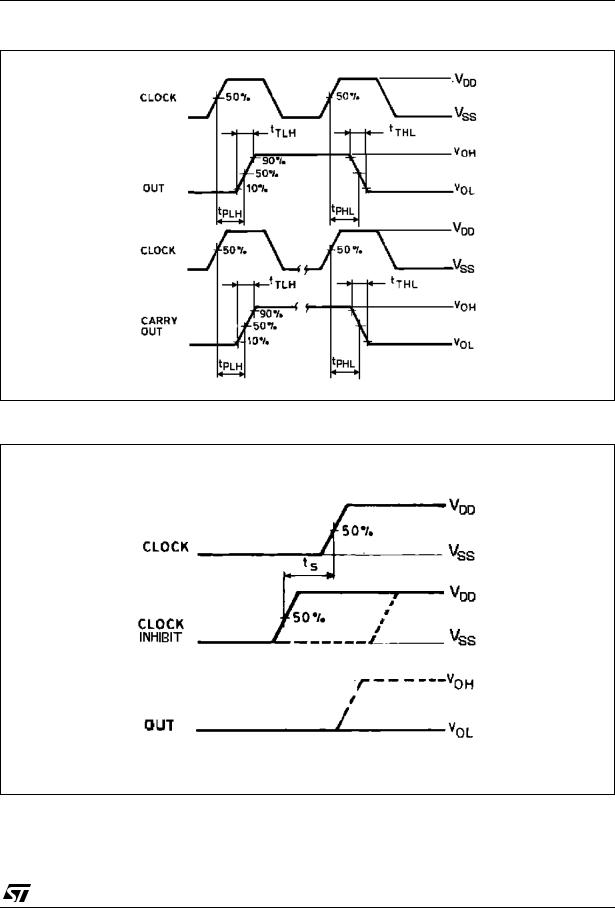
WAVEFORM 1 : PROPAGATION DELAY TIMES (f=1MHz; 50% duty cycle)
WAVEFORM 2 : MINIMUM SETUP TIME (CLOCK INHIBIT TO CLOCK) (f=1MHz; 50% duty cycle)
7/11
HCF4017B
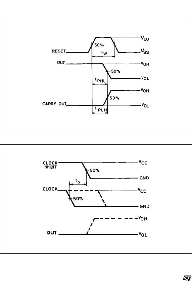
WAVEFORM 3 : PROPAGATION DELAY TIMES, MINIMUM RESET PULSE WIDTH (f=1MHz; 50% duty cycle)
WAVEFORM 4 : MINIMUM SETUP TIME (CLOCK TO CLOCK INHIBIT) (f=1MHz; 50% duty cycle)
8/11
|
|
|
|
|
|
|
HCF4017B |
|
|
|
|
|
|||
|
|
|
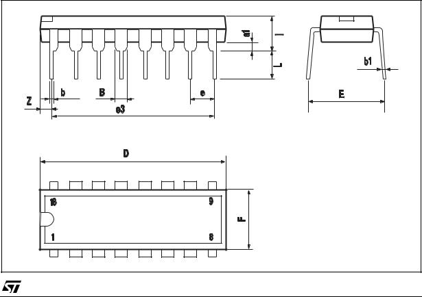
Plastic DIP-16 (0.25) MECHANICAL DATA |
|
|||
|
|
|
|
|
|
|
|
|
|
|
|
|
|
|
|
DIM. |
|
|
mm. |
|
|
inch |
|
|
|
|
|
|
|
|
|
|
MIN. |
TYP |
MAX. |
MIN. |
TYP. |
MAX. |
|
|
|
||||||
|
|
|
|
|
|
|
|
a1 |
0.51 |
|
|
0.020 |
|
|
|
|
|
|
|
|
|
|
|
B |
0.77 |
|
1.65 |
0.030 |
|
0.065 |
|
|
|
|
|
|
|
|
|
b |
|
0.5 |
|
|
0.020 |
|
|
|
|
|
|
|
|
|
|
b1 |
|
0.25 |
|
|
0.010 |
|
|
|
|
|
|
|
|
|
|
D |
|
|
20 |
|
|
0.787 |
|
|
|
|
|
|
|
|
|
E |
|
8.5 |
|
|
0.335 |
|
|
|
|
|
|
|
|
|
|
e |
|
2.54 |
|
|
0.100 |
|
|
|
|
|
|
|
|
|
|
e3 |
|
17.78 |
|
|
0.700 |
|
|
|
|
|
|
|
|
|
|
F |
|
|
7.1 |
|
|
0.280 |
|
|
|
|
|
|
|
|
|
I |
|
|
5.1 |
|
|
0.201 |
|
|
|
|
|
|
|
|
|
L |
|
3.3 |
|
|
0.130 |
|
|
|
|
|
|
|
|
|
|
Z |
|
|
1.27 |
|
|
0.050 |
|
|
|
|
|
|
|
|
|
P001C |
9/11 |
HCF4017B
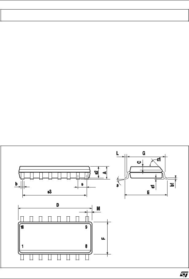
SO-16 MECHANICAL DATA
DIM. |
|
|
mm. |
|
|
|
inch |
|
|
|
|
|
|
|
|
|
|
|
MIN. |
TYP |
MAX. |
|
MIN. |
TYP. |
MAX. |
|
|
|
|
||||||
|
|
|
|
|
|
|
|
|
A |
|
|
1.75 |
|
|
|
0.068 |
|
|
|
|
|
|
|
|
|
|
a1 |
0.1 |
|
0.2 |
|
0.003 |
|
0.007 |
|
|
|
|
|
|
|
|
|
|
a2 |
|
|
1.65 |
|
|
|
0.064 |
|
|
|
|
|
|
|
|
|
|
b |
0.35 |
|
0.46 |
|
0.013 |
|
0.018 |
|
|
|
|
|
|
|
|
|
|
b1 |
0.19 |
|
0.25 |
|
0.007 |
|
0.010 |
|
|
|
|
|
|
|
|
|
|
C |
|
0.5 |
|
|
|
0.019 |
|
|
|
|
|
|
|
|
|
|
|
c1 |
|
|
|
45° (typ.) |
|
|
||
|
|
|
|
|
|
|
|
|
D |
9.8 |
|
10 |
|
0.385 |
|
0.393 |
|
|
|
|
|
|
|
|
|
|
E |
5.8 |
|
6.2 |
|
0.228 |
|
0.244 |
|
|
|
|
|
|
|
|
|
|
e |
|
1.27 |
|
|
|
0.050 |
|
|
|
|
|
|
|
|
|
|
|
e3 |
|
8.89 |
|
|
|
0.350 |
|
|
|
|
|
|
|
|
|
|
|
F |
3.8 |
|
4.0 |
|
0.149 |
|
0.157 |
|
|
|
|
|
|
|
|
|
|
G |
4.6 |
|
5.3 |
|
0.181 |
|
0.208 |
|
|
|
|
|
|
|
|
|
|
L |
0.5 |
|
1.27 |
|
0.019 |
|
0.050 |
|
|
|
|
|
|
|
|
|
|
M |
|
|
0.62 |
|
|
|
0.024 |
|
|
|
|
|
|
|
|
|
|
S |
|
|
|
8° (max.) |
|
|
||
|
|
|
|
|
|
|
|
|
PO13H |
10/11 |