|
DICOM PS3.3 2020a - Information Object Definitions |
Page 1351 |
Attribute Name |
Tag |
Type |
Attribute Description |
|
Swivel Range |
(0070,1A06) |
1C |
Range in which a volume rotates back-and-forth around the swivel axis, |
in degrees. The initial position is at the midpoint of the swivel range. See Section C.11.29.1.
Required if Presentation Animation Style (0070,1A01) is SWIVEL.
C.11.29.1 Presentation Animation Style
The presence of Presentation Animation Style (0070,1A01) indicates that a form of view animation is intended by the creator of the Presentation State, and the value of the Attribute indicates the nature of such animation. See Section FF.2.4.2 “Volumetric Animation” in PS3.4 for further description of the various presentation animation styles.
Values of Presentation Animation Style (0070,1A01) are:
INPUT_SEQ |
A number of inputs are displayed sequentially using the same Presentation State. The inputs are described |
|
byItemsinVolumetricPresentationStateInputSequence(0070,1201)withvaluesofInputSequencePosition |
|
Index (0070,1203). If Recommended Animation Rate (0070,1A03) is present, the animation occurs as values |
|
of the sequence position index are incremented at a rate specified by Recommended Animation Rate |
|
(0070,1A03) in units of steps per second. If Recommended Animation Rate (0070,1A03) is not present, the |
|
use of manual scrolling or animation rate is at the discretion of the display application. Inputs with the same |
|
InputSequencePositionIndex(0070,1203)valuearedisplayedsimultaneously.IfallvaluesofInputSequence |
|
Position Index (0070,1203) are the same, the presented view is not animated. |
PRESENTATION_SEQThe animation is determined by two or more Presentation States sharing the same value of Presentation Sequence Collection UID (0070,1102). The Presentation States shall be applied sequentially in the order of Presentation Sequence Position Index (0070,1103) values as the index is varied at a rate specified by Re- commended Animation Rate (0070,1A03) in units of steps per second, if present; otherwise, the use of manual scrolling or animation rate is at the discretion of the display application.
CROSSCURVE Indicates that the designated Planar MPR view shall be stepped along the curve defined in Animation Curve Sequence (0070,1A04) at the interval specified by Animation Step Size (0070,1A05). The rate is specified by Recommended Animation Rate (0070,1A03) in units of steps per second, if present; otherwise, the use of manual scrolling or animation rate is at the discretion of the display application.
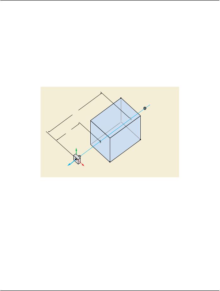
FLYTHROUGH Indicates that the field of view defined by Render Field of View (0070,1606) be stepped along the curve defined in Animation Curve Sequence (0070,1A04) at the rate specified by Recommended Animation Rate (0070,1A03) steps per second. Presentation Animation Style (00070,1A01) value of FLYTHROUGH shall be present only if Render Projection (0070,1602) is present.
Viewpoint LookAt Point (0070,1604) shall coincide with the first point in Volumetric Curve Points (0070,150D, the direction from the Viewpoint Position (0070,1603) to the Viewpoint LookAt Point(0070,1604) shall be tangent to the curve at that point, and the Viewpoint Up Direction (0070,1605) shall be parallel to the first direction cosine in Volumetric Curve Up Directions (0070,1A07).
Note
These conditions ensure the view defined by the Volumetric Presentation State matches the initial view of the animation.
SpacingofcurvepointsinVolumetricCurvePoints(0070,150D)shallbechosensuchthattheangularchange betweenanytwoconsecutivedirectioncosinesinVolumetricCurveUpDirections(0070,1A07)isalwaysless than 90 degress in 3D space, and should be chosen such that the change in curve direction at each point is reasonably small.
Note
This condition and recommendation ensure that the up direction interpolated between points in Volumetric Curve Points (0070,150D) and the direction along the tangent from viewpoint to lookAt point at each step are always unambiguous.


 Viewpoint LookAt Point