Page 1340 |
DICOM PS3.3 2020a - Information Object Definitions |
MPR View Width Direction (0070,x507)
MPR View Width (0070,x508)
MPR Top Left Hand Corner (0070,x505)
MPR View Height (0070,x512)
MPR View Height Direction (0070,x511)
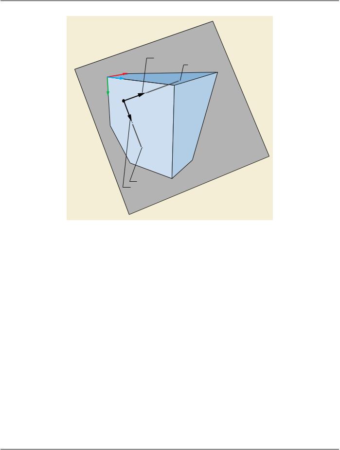
Figure C.11.26-2. Planar MPR THIN Geometry
The following Attributes describe the PLANAR MPR:
•MPRViewWidthDirection(0070,1507)andMPRViewHeightDirection(0070,1511)specifytheorientationoftheMPRviewrectangle in the Volumetric Presentation State Reference Coordinate System
•MPR View Width (0070,1508) and MPR View Height (0070,1512) specify the size of the MPR view rectangle in the Volumetric Presentation State Reference Coordinate System
•MPR Top Left Hand Corner (0070,1505) species the position of the upper-left corner of the MPR view rectangle in the Volumetric Presentation State Reference Coordinate System
•MPR Thickness Type (0070,1502) specifies whether the MPR is created by taking a single sample for each pixel (THIN) or by creating an orthographic rendering of a slab volume with a defined thickness using the method defined by Rendering Method (0070,120D) (SLAB).Ifthespecified thickness is belowanapplication-determinedlimitthe resultingview shallbe treated as aTHIN MPR.
•MPR Slab Thickness (0070,1503) specifies the thickness of the slab if MPR Thickness Type (0070,1502) is SLAB. The slab volume is positioned such that the MPR view defined by MPR View Width Direction (0070,1507), MPR View Width (0070,1508), MPR View Height Direction (0070,1511), MPR View Height (0070,1512), and MPR Top Left Hand Corner (0070,1505) is at the midpoint of the slab thickness.