Материал: part03

Внимание! Если размещение файла нарушает Ваши авторские права, то обязательно сообщите нам


DICOM PS3.3 2020a - Information Object Definitions​

Page 711​

Attribute Name​

Tag​

Type​


Attribute Description​


>>General Accessory​

(300A,0422)​

3​

User supplied description of General Accessory.​


Description​


>>General Accessory Type​

(300A,0423)​

3​

Specifies the type of accessory.​


Defined Terms:​


GRATICULE​

Accessory tray with a radio-opaque grid​


IMAGE_DETECTOR​Image acquisition device positioned in the beam​


line​


RETICLE​

Accessory tray with radio-transparent markers or​


grid​


>>Accessory Code​

(300A,00F9)​

3​

Machine-readable identifier for this accessory​


>>Source to General​

(300A,0425)​

3​

Radiation source to general accessory distance (in mm) for current​

Accessory Distance​


accessory.​


>Number of Blocks​

(300A,00F0)​

1​

Number of shielding blocks associated with Beam.​


>Block Sequence​

(300A,00F4)​

2C​

SequenceofblocksassociatedwithBeam.RequiredifNumberofBlocks​


(300A,00F0) is non-zero.​


Zero or more Items shall be included in this Sequence.​


>>Block Tray ID​

(300A,00F5)​

3​

User-supplied identifier for block tray.​


>>Tray Accessory Code​

(300A,0355)​

3​

An identifier for the Tray intended to be read by a device such as a​


bar-code reader.​


>>Accessory Code​

(300A,00F9)​

3​

An identifier for the Block intended to be read by a device such as a​


bar-code reader.​


>>Source to Block Tray​

(300A,00F6)​

2​

Radiation Source to attachment edge of block tray assembly (mm).​

Distance​


>>Block Type​

(300A,00F8)​

1​

Type of block.​


Enumerated Values:​


SHIELDING​blocking material is inside contour​


APERTURE​blocking material is outside contour​


>>Block Divergence​

(300A,00FA)​

2​

Indicates presence or otherwise of geometrical divergence​


Enumerated Values:​


PRESENT​block edges are shaped for beam divergence​


ABSENT​block edges are not shaped for beam divergence​

>>Block Mounting Position​

(300A,00FB)​

3​

Indicates on which side of the Block Tray the block is mounted.​


Enumerated Values:​


PATIENT_SIDE​the block is mounted on the side of the Block Tray​


that is towards the patient.​


SOURCE_SIDE​the block is mounted on the side of the Block Tray​


that is towards the radiation source.​


>>Block Number​

(300A,00FC)​

1​

Identification Number of the Block. The value of Block Number​


(300A,00FC) shall be unique within the Beam in which it is created.​

>>Block Name​

(300A,00FE)​

3​

User-defined name for block.​


>>Material ID​

(300A,00E1)​

2​

User-supplied identifier for material used to manufacture Block.​

>>Block Thickness​

(300A,0100)​

3​

Physical thickness of block (in mm) parallel to radiation beam axis.​

>>Block Number of Points​

(300A,0104)​

2​

Number of (x,y) pairs defining the block edge.​


- Standard -​

Page 712​

DICOM PS3.3 2020a - Information Object Definitions​

Attribute Name​

Tag​

Type​

Attribute Description​

>>Block Data​

(300A,0106)​

2​

A data stream of (x,y) pairs that comprise the block edge. The number​


of pairs shall be equal to Block Number of Points (300A,0104), and the​


vertices shall be interpreted as a closed polygon. Coordinates are​


projected onto the machine isocentric plane in the IEC BEAM LIMITING​


DEVICE coordinate system (mm).​

Fluence Map Sequence​

(3002,0040)​

1C​

A Sequence of data describing the fluence map Attributes for a​


radiotherapy beam.​


Only a single Item shall be included in this Sequence.​


Required if the third value of Image Type (0008,0008) is FLUENCE.​

>Fluence Data Source​

(3002,0041)​

1​

Source of fluence data.​


Enumerated Values:​


CALCULATED​Calculated by a workstation​


MEASURED​ Measured by exposure to a film or detector.​

>Fluence Data Scale​

(3002,0042)​

3​

The Meterset corresponding with a fluence map cell value of 1.0​


expressed in units specified by Primary Dosimeter Units (300A,00B3).​


This is the Meterset value used for treatment, not the Meterset used to​


expose the film as defined by Meterset Exposure (3002,0032).​

Gantry Angle​

(300A,011E)​

3​

Treatment machine gantry angle, i.e., orientation of IEC GANTRY​


coordinate system with respect to IEC FIXED REFERENCE coordinate​


system (degrees).​

Gantry Pitch Angle​

(300A,014A)​

3​

Gantry Pitch Angle. i.e., the rotation of the IEC GANTRY coordinate​


system about the X-axis of the IEC GANTRY coordinate system​


(degrees). See Section C.8.8.25.6.5.​

BeamLimitingDeviceAngle​

(300A,0120)​

3​

Treatment machine beam limiting device (collimator) angle, i.e.,​


orientation of IEC BEAM LIMITING DEVICE coordinate system with​


respect to IEC GANTRY coordinate system (degrees).​

Patient Support Angle​

(300A,0122)​

3​

Patient Support angle, i.e., orientation of IEC PATIENT SUPPORT​


coordinate system with respect to IEC FIXED REFERENCE coordinate​


system (degrees).​

Table Top Eccentric Axis​

(300A,0124)​

3​

Distance (positive) from the IEC PATIENT SUPPORT vertical axis to​

Distance​


the IEC TABLE TOP ECCENTRIC vertical axis (mm).​

Table Top Eccentric Angle​

(300A,0125)​

3​

Table Top (non-isocentric) angle, i.e., orientation of IEC TABLE TOP​


ECCENTRICcoordinatesystemwithrespecttoIECPATIENTSUPPORT​


system (degrees).​

Table Top Pitch Angle​

(300A,0140)​

3​

TableTopPitchAngle,i.e.,therotationoftheIECTABLETOPcoordinate​


system about the X-axis of the IEC TABLE TOP coordinate system​


(degrees). See Section C.8.8.25.6.2.​

Table Top Roll Angle​

(300A,0144)​

3​

TableTopRollAngle,i.e.,therotationoftheIECTABLETOPcoordinate​


system about the Y-axis of the IEC TABLE TOP coordinate system​


(degrees). See Section C.8.8.25.6.2.​

Table Top Vertical Position​

(300A,0128)​

3​

TableTopVerticalpositioninIECTABLETOPcoordinatesystem(mm).​

Table Top Longitudinal​

(300A,0129)​

3​

Table Top Longitudinal position in IEC TABLE TOP coordinate system​

Position​


(mm).​

Table Top Lateral Position​

(300A,012A)​

3​

Table Top Lateral position in IEC TABLE TOP coordinate system (mm).​

Isocenter Position​

(300A,012C)​

3​

Isocentercoordinates(x,y,z),inmm.Specifiesthelocationofthemachine​


isocenter in the Patient-Based Coordinate System associated with the​


Frame of Reference. It allows transformation from the equipment-based​


IEC coordinate system to the Patient-Based Coordinate System.​

- Standard -​


DICOM PS3.3 2020a - Information Object Definitions​

Page 713​

Attribute Name​

Tag​

Type​

Attribute Description​


Patient Position​

(0018,5100)​

1C​

Patient position descriptor relative to the patient support device.​


Required if Isocenter Position (300A,012C) is present. May be present​


otherwise.​


See Section C.8.8.12.1.2 for Defined Terms and further explanation.​

Note​

The orientation of the patient relative to the patient support​ device is denoted in the same manner as in the RT Patient​ Setup Module. It defines the relation of the DICOM​ Patient-Based Coordinate System identified by the Frame of​ Reference Module of the RT Image to the IEC coordinate​ systemandtogetherwithIsocenterPosition(300A,012C)allows​ theRTImagetobeplacedintothePatientFrameofReference.​ It also allows a system using an RT Image to verify that the​ patient is setup in a similar position relative to the patient​ support device.​

Exposure Time​

(0018,1150)​

3​ Time of X-Ray exposure (msec). Required if Value 3 of Image Type​


(0008,0008) is SIMULATOR or RADIOGRAPH. May be present​


otherwise.​


See Section C.8.8.2.8.​

Exposure Time in ms​

(0018,9328)​

3​ Duration of X-Ray exposure in msec.​


See Section C.8.8.2.8.​

Meterset Exposure​

(3002,0032)​

3​ Treatment machine Meterset duration over which image has been​

acquired,specifiedinMonitorunits(MU)orminutesasdefinedbyPrimary​ Dosimeter Unit (300A,00B3).​

See Section C.8.8.2.8.​

Note​

1.​The numeric beam data parameters recorded with the RT Image correspond to the parameters as they were known at​ the time the image was created or taken. The parameters may or may not correspond to an actual RT Plan instance​ that is created for a patient. If the Reported Values Origin (3002,000A) has an Enumerated Value of OPERATOR or​ ACTUAL and there is an RT Plan reference present, the numeric beam data parameters may or may not be the same​ in the two objects.​

2.​The Z coordinate of the X-Ray Image Receptor Translation (3002,000D) will be equal to the Radiation Machine SAD​ (3002,0022)minustheRTImageSID(3002,0026).Iftheimagereceptorisfurtherfromthebeamsourcethanthemachine​ isocenter, the Z coordinate will be negative (see IEC 61217).​

C.8.8.2.1 Multi-frame Image Data​

In either multiple exposure multi-frame images or cine images, only the Attributes inside Exposure Sequence (3002,0030) shall differ​ between frames. For example, Attributes such as beam limiting device (collimator) leaf (element) positions and block information may​ change, whereas Attributes such as gantry and beam limiting device (collimator) angle shall not change.​

C.8.8.2.2 X-Ray Image Receptor Angle​

TheX-RayImageReceptorAngle(3002,000E)specifiestherotationoftheimagereceptordeviceintheIECX-RAYIMAGERECEPTOR​ PLANE. A positive angle corresponds to a counter-clockwise rotation of the X-Ray Image Receptor as viewed from the radiation​ source in the IEC GANTRY coordinate system. The normal (non-rotated) value for this parameter is zero degrees.​

- Standard -​

Page 714​

DICOM PS3.3 2020a - Information Object Definitions​

C.8.8.2.3 Image Plane Pixel Spacing and RT Image SID​

TheImagePlanePixelSpacing(3002,0011)Attributeshallalwaysbedefinedontheimageplane,i.e.,attheradiationmachinesource​ toimageplanedistancespecifiedbyRTImageSID(3002,0026).Forimageswherethesource-imagedistanceisundefinedorunknown​ (e.g., DRR images), RT Image SID (3002,0026) shall equal Radiation Machine SAD (3002,0022) and Image Plane Pixel Spacing​ (3002,0011) shall be defined on this common plane.​

C.8.8.2.4 Exposure Sequence​

Exposure Sequence (3002,0030) allows specification of imaging parameters and aperture definitions for single exposure images​ (single Item Sequence), integrated images (multiple Item Sequence) or multiple exposures (multiple Item Sequence). An integrated​ image is a single-frame image (no Cine Module or Multi-frame Module present) with multiple Items in the Exposure Sequence. A​ Referenced Frame Number (0008,1160) is not provided. A multiple exposure image can be expressed as a multi-frame image con-​ taining either a single frame, or more than one frame. Referenced Frame Number (0008,1160) shall be specified for each Exposure​ Sequence (3002,0030) Item for multiple exposure images expressed using more than one frame.​

Many of the Attributes referring to beam parameters can be present both inside Exposure Sequence (3002,0030) and outside the​ Sequence.WhenaspecificAttributeispresentinsidetheSequence,thatAttributeshallsupersedetheAttributefoundoutsideExposure​ Sequence (3002,0030). For any Item in the Sequence, if the Attribute is not present, the value of the Attribute (if specified) outside​ the Sequence shall be used.​

C.8.8.2.5 Single-Frame and Multi-frame Images​

If the Multi-frame Module is present and the Cine Module is not present then the Frame Increment Pointer (0028,0009) shall have​ the Enumerated Value of 00200013 (Instance Number). If the Multi-frame Module and Cine Module are both present then the Frame​ Increment Pointer (0028,0009) shall have an Enumerated Value of either 00181063 (Frame Time) or 00181065 (Frame Time Vector).​

C.8.8.2.6 Image Pixel Module Attributes​

C.8.8.2.6.1 Samples Per Pixel​

Enumerated Values:​

1​

C.8.8.2.6.2 Photometric Interpretation​

Enumerated Values:​

MONOCHROME2​

C.8.8.2.6.3 Bits Allocated​

Enumerated Values:​

8​

16​

C.8.8.2.6.4 Bits Stored​

Enumerated Values when Bits Allocated (0028,0100) is 8:​

8​

Enumerated Values when Bits Allocated (0028,0100) is 16:​

12​

13​

14​

15​

16​

C.8.8.2.6.5 High Bit​

For RT Images, High Bit (0028,0102) shall be one less than the value of Bits Stored (0028,0101).​

- Standard -​

DICOM PS3.3 2020a - Information Object Definitions​

Page 715​

C.8.8.2.6.6 Pixel Representation​

Enumerated Values when Bits Allocated (0028,0100) is 8:​

0000H​unsigned integer​

C.8.8.2.7 RT Image Plane, Position and Orientation​

When RT Image Plane (3002,000C) is NORMAL and RT Image Orientation (3002,0010) is not provided, the orientation is defined as​ follows: The image viewing direction shall be from the radiation source to the image (i.e., in the sense of a beam's eye view, or along​ the negative Zr direction of the IEC X-RAY IMAGE RECEPTOR coordinate system).​

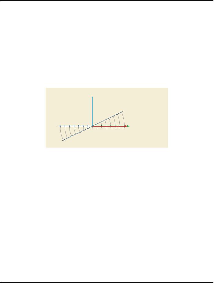
If RT Image Plane is NON_NORMAL, any rotation defined by RT Image Orientation is performed about the origin of the IEC X-RAY​ IMAGE RECEPTOR coordinate system. The definitions of the x and y coordinates of the RT Image Position (3002,0012) are defined​ before any rotation of the image plane is taken into account, see Figure C.8.8.2.7-1.​

The direction of rows shall be along the positive Xr direction and the direction of the columns shall be along the negative Yr direction​ of the IEC X-RAY IMAGE RECEPTOR coordinate system.​

IEC X-ray Image Receptor Z-Axis

+Zr

IEC X-ray Image Receptor Plane

+Xr, +Yr

Non-normal Image Plane

Figure C.8.8.2.7-1. Non-normal Image Plane​

C.8.8.2.8 Exposure Time and Meterset Exposure​

Multi-frame RT Images may encode a continuous acquisition. In this case, the Exposure Sequence (3002,0030) may not reference​ all frames.​

The Attributes Exposure Time (00018,1150), Exposure Time in ms (0018,9328) and Meterset Exposure (3002,0032) Attributes in the​ Exposure Sequence (3002,0030), if present with values, contain the exposure values encompassing the X-Ray exposure during the​ acquisition of the single frame referenced by the Referenced Frame Number (0008,1160). Note that not all frames may be referenced​ in this Sequence and therefore the sum of these values may not equal the total exposure value.​

TheAttributesExposureTime(00018,1150),ExposureTimeinms(0018,9328)andMetersetExposure(3002,0032)Attributesoutside​ the Exposure Sequence (3002,0030) may be used to record the total exposure values.​

C.8.8.3 RT Dose Module​

The RT Dose Module is used to convey 2D or 3D radiation dose data generated from treatment planning systems or similar devices.​ The Attributes defined within the Module support dose for a single radiation beam (potentially comprised of multiple segments, as​ deliveredinadynamictreatment)oragroupofbeamscomprisingeitherafractiongroup(seeSectionC.8.8.13)oracompletetreatment​ plan (potentially the sum of multiple fraction groups).​

The RT Dose Module provides the mechanism to transmit a 3D array of dose data as a set of 2D dose planes that may or may not​ be related to CT or MR image planes. This mechanism works via the DICOM Multi-frame Module that is required if multi-frame pixel​ data are present.​

- Standard -​