Материал: part03

Внимание! Если размещение файла нарушает Ваши авторские права, то обязательно сообщите нам

DICOM PS3.3 2020a - Information Object Definitions​

Page 541​

Item, the Applicable Frame Range is assumed to end at the last frame number of the image minus​ Contrast Frame Averaging (0028,6112) plus one;​
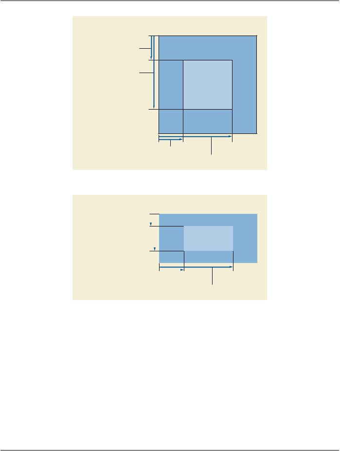
TID​ (Time Interval Differencing) The mask for each frame within the Applicable Frame Range​ (0028,6102) is selected by subtracting TID Offset (0028,6120) from the respective frame number.​ If the Applicable Frame Range is not present in this Sequence Item, the Applicable Frame Range​ is assumed to be a range where TID offset subtracted from any frame number with the range​ results in a valid frame number within the Multi-frame image.​

Note​

A positive value for TID Offset (0028,6120) means that the mask frame numbers are​ lower than the subtracted frame numbers. A negative TID Offset means that the mask​ frame numbers are higher than the subtracted frame numbers.​

REV_TID​ (Reversed Time Interval Differencing) The number of the mask frame for each contrast frame​ withintheApplicableFrameRange(0028,6102)iscalculatedbysubtractingTIDOffset(0028,6120)​ fromthefirstframewithintheApplicableFrameRange,TIDOffset(0028,6120)+2fromthesecond​ frame within the Applicable Frame Range, TID Offset (0028,6120) +4 from the third frame and so​ on. The Applicable Frame Range (0028,6102) shall be present.​

When multiple pairs of frame numbers are specified in the Applicable Frame Range Attribute, the​ beginning frame numbers (i.e., the first frame number in each pair) shall be in increasing order.​

Algorithm to calculate the Mask Frame Number:​

MFN = (FCFN - TID Offset) - (CFN - FCFN)​

Where:​

MFN = Mask Frame Number​

CFN = Contrast Frame Number​

FCFN = First Contrast Frame Number, the first frame number of the first pair in the Applicable​

Frame Range​

Note​

A positive value for TID Offset (0028,6120) means that the mask frame numbers are​ lower than the subtracted frame numbers. A negative TID Offset means that the mask​ frame numbers are higher than the subtracted frame numbers.​

Note​

Example of TID Offset, see Figure C.7.6.10-1:​


Preceding


Mask


Gap


Contrast

Trailing


Frames


Frames


Frames


Frames

Frames


1

2

3

4

5


10


15

16


19

20


30


32


Rev TID Offset

Figure C.7.6.10-1. Example of TID Offset​

Number of Frames: 32​

Applicable Frame Range: 20 to 30​

TID Offset: 5​

For Calculating the TID Offset for Mask Operation REV_TID see Table C.7.6.10-1.​

- Standard -​

Page 542​ DICOM PS3.3 2020a - Information Object Definitions​

Table C.7.6.10-1. Example Mask Frame Numbers for Mask Operation REV_TID​

Contrast Frame Number (CFN) (Absolute value)​

Mask Frame Number (MFN) (Absolute value)​

20​

15​

21​

14​

22​

13​

…​

…​

28​

7​

29​

6​

30​

5​

In this example the acquisition of the mask frames starts with frame 5 and ends with frame 15. The acquisition of the contrast​ frames starts with frame 20 and ends with frame 30 (Applicable Frame Range). The number 5 for TID Offset indicates a gap​ between "end of mask frames" and "begin of contrast frames" of 4 frames, e.g., injection phase and/or time needed to drive​ C-arm in reverse. Additionally, in this example, the first 4 frames and the last two frames are not used for this Reversed Time​ Interval Differencing loop.​

C.7.6.10.1.2 Mask Sub-pixel Shift​

A pair of floating point numbers specifying the fractional vertical [adjacent row spacing] and horizontal [adjacent column spacing] pixel​ shift applied to the mask before subtracting it from the contrast frame. The row offset results in a shift of the pixels along the column​ axis. The column offset results in a shift of the pixels along the row axis. A positive row offset is a shift toward the pixels of the lower​ row of the pixel plane. A positive column offset is a shift toward the pixels of the left hand side column of the pixel plane.​

C.7.6.11 Display Shutter Module​

TheDisplayshutterisageometricmaskconsistingofoneormorecombinedshapesthatmaybeappliedontheimageforpresentation​ purposesinordertoneutralizethedisplayofanyofthepixelslocatedoutsideoftheshuttershape.Geometryoftheshutterisspecified​ with respect to a row and column coordinate system where the origin is the upper left hand pixel. This origin is specified by the values​ 1,1 for row/column. A row coordinate represents a row spacing (vertical) and a column coordinate represents a column spacing (ho-​ rizontal). Up to three different shutter shapes may be used and superimposed.​

The manner in which the display area is neutralized (black-out, gray, or other means) is defined by the Attribute Shutter Presentation​ Value (0018,1622), or undefined if this Attribute is absent or empty.​

Table C.7-17. Display Shutter Module Attributes​

Attribute Name​ Tag​ Type​ Attribute Description​

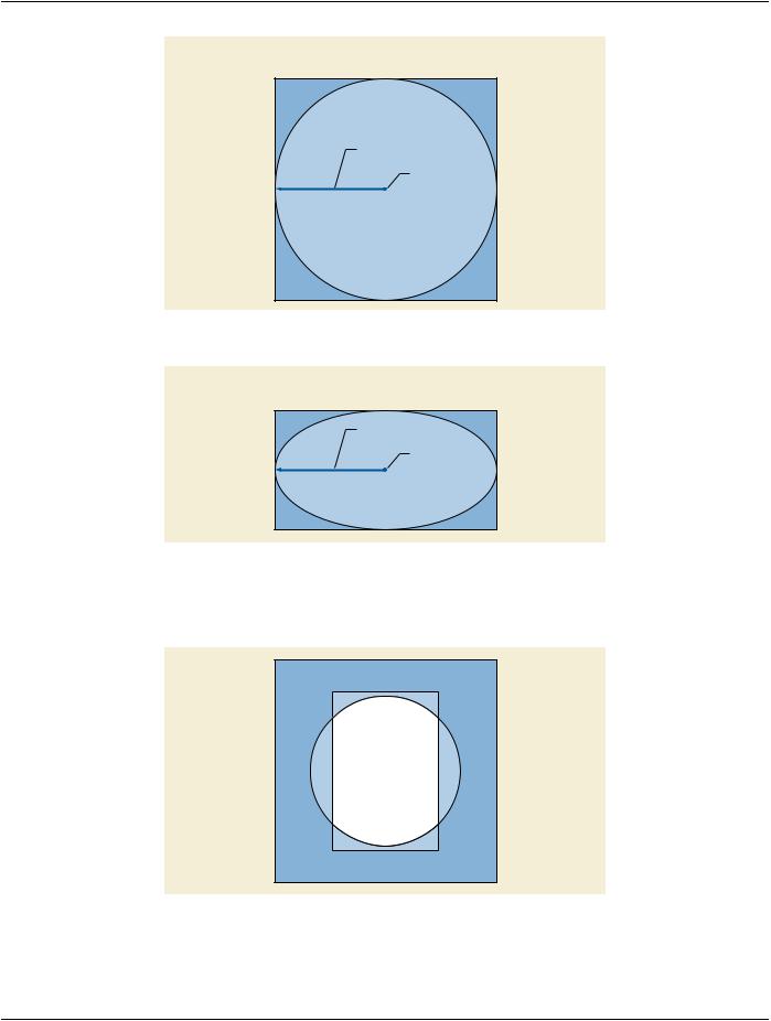
Include Table C.7-17a “Display Shutter Macro Attributes”​

Table C.7-17a. Display Shutter Macro Attributes​

Attribute Name​

Tag​

Type​

Attribute Description​

Shutter Shape​

(0018,1600)​

1​

Shape(s) of the shutter defined for display.​

Enumerated Values:​

RECTANGULAR​

CIRCULAR​

POLYGONAL​

This multi-valued Attribute shall contain at most one of each Enumerated​ Value. When multiple values are present, and the shutter is applied to a​ displayed image, then all of the shapes shall be combined and applied​ simultaneously, that is, the least amount of image remaining shall be visible​ (unoccluded). See Figure C.7-4b.​

- Standard -​


DICOM PS3.3 2020a - Information Object Definitions​

Page 543​

Attribute Name​

Tag​

Type​

Attribute Description​


Shutter Left Vertical Edge​

(0018,1602)​

1C​

Required if Shutter Shape (0018,1600) is RECTANGULAR. Location of the​


left edge of the rectangular shutter with respect to pixels in the image given​


as column.​


Shutter Right Vertical​

(0018,1604)​

1C​

Required if Shutter Shape (0018,1600) is RECTANGULAR. Location of the​

Edge​


right edge of the rectangular shutter with respect to pixels in the image given​


as column.​


Shutter Upper Horizontal​

(0018,1606)​

1C​

Required if Shutter Shape (0018,1600) is RECTANGULAR. Location of the​

Edge​


upperedgeoftherectangularshutterwithrespecttopixelsintheimagegiven​


as row.​


Shutter Lower Horizontal​

(0018,1608)​

1C​

Required if Shutter Shape (0018,1600) is RECTANGULAR. Location of the​

Edge​


loweredgeoftherectangularshutterwithrespecttopixelsintheimagegiven​


as row.​


Center of Circular Shutter​

(0018,1610)​

1C​

Required if Shutter Shape (0018,1600) is CIRCULAR. Location of the center​


of the circular shutter with respect to pixels in the image given as row and​


column.​


Radius of Circular Shutter​

(0018,1612)​

1C​

Required if Shutter Shape (0018,1600) is CIRCULAR. Radius of the circular​


shutter with respect to pixels in the image given as a number of pixels along​


the row direction.​


Vertices of the Polygonal​

(0018,1620)​

1C​

Required if Shutter Shape (0018,1600) is POLYGONAL.​


Shutter​


Multiple Values where the first set of two values are:​


row of the origin vertex\column of the origin vertex​


Two or more pairs of values follow and are the row and column coordinates​


of the other vertices of the polygon shutter. Polygon shutters are implicitly​


closed from the last vertex to the origin vertex and all edges shall be​


non-intersecting except at the vertices.​


ShutterPresentationValue​

(0018,1622)​

3​

A single gray unsigned value used to replace those parts of the image​


occludedbytheshutter,whenrenderedonamonochromedisplay.Theunits​


arespecifiedinP-Values,fromaminimumof0000H(black)uptoamaximum​


of FFFFH (white).​


Note​


The maximum P-Value for this Attribute may be different from the​


maximum P-Value from the output of the Presentation LUT, which​


may be less than 16 bits in depth.​


ShutterPresentationColor​

(0018,1624)​

3​

A color triplet value used to replace those parts of the image occluded by the​

CIELab Value​


shutter, when rendered on a color display. The units are specified in​


PCS-Values, and the value is encoded as CIELab. See Section C.10.7.1.1.​

Figure C.7-1, Figure C.7-2, Figure C.7-3, Figure C.7-4 and Figure C.7-4b illustrate the values of coordinate Attributes for 1:1 aspect​ and 2:1 aspect ratio images with rectangular and circular display shutters applied.​

- Standard -​

Page 544​

DICOM PS3.3 2020a - Information Object Definitions​

Image Matrix

Columns: 1024

Rows: 1024

Upper Horizontal Edge (0018,1606)

Value: 256

Display Area

• Columns: 512

Lower Horizontal Edge (0018,1608) • Rows: 512

Value: 768

Left Vertical Edge (0018,1602)

Value: 256

Right Vertical Edge (0018,1604)

Value: 768

Figure C.7-1. Rectangular Display Shutter (1:1 aspect ratio image)​


Image Matrix


• Columns: 1024


• Rows: 512

Upper Horizontal Edge (0018,1606)


Value: 256


Lower Horizontal Edge (0018,1608)


Display Area


Value: 768


• Columns: 512


• Rows: 256


Left Vertical Edge (0018,1602)

Value: 256

Right Vertical Edge (0018,1604)

Value: 768

Figure C.7-2. Rectangular Display Shutter (2:1 aspect ratio images as they would appear before​ interpolation for display)​

- Standard -​

DICOM PS3.3 2020a - Information Object Definitions​

Page 545​

Image Matrix

Columns: 1024

Rows: 1024

Radius (0018, 1612)

Value: 512

Center (0018, 1610)

Value: 512 \ 512

Figure C.7-3. Circular Display Shutter (1:1 aspect ratio image)​

Image Matrix

Columns: 1024

Rows: 512

Radius (0018, 1612)

Value: 512

Center (0018, 1610)

Value: 256 \ 512

FigureC.7-4.CircularDisplayShutter(2:1aspectratioimagesastheywouldappearbeforeinterpolation​

for display)​

FigureC.7-4billustratesthecombinedapplicationofrectangularandcirculardisplayshutterstoshowtheleastamountofvisibleimage.​

Figure C.7-4b. Combined Rectangular and Circular Display Shutter​

- Standard -​