Материал: m912201e

Внимание! Если размещение файла нарушает Ваши авторские права, то обязательно сообщите нам

The UTIL.LIB Library

339

Controllers


14.5 Controllers

14.5.1P

The P controller function block:

ACTUAL (actual value) and DESIRED (desired or nominal value) as well as KP, the proportionality coefficient, are all input values of the type REAL.

The output, the absolute control output (OUT), is of the type REAL, and is calculated as follows:

OUT ACTUAL KP ,

whereby =DESIRED-ACTUAL.

Example in FBD:

14.5.2PD

The PD controller function block:

ACTUAL (actual value) and DESIRED (desired or nominal value) as well as KP, the proportionality coefficient, are all input values of the type REAL. TD is of the type DWORD and contains the derivative action time in msec.

RESET is of the type BOOL and serves to reset the controller.

The output, the absolute control output (OUT), is of the type REAL, and is calculated as follows:


TD


OUT ACTUAL KP


t ,

whereby =DESIRED-ACTUAL. Example in FBD:

WAGO-I/O-SYSTEM 759 WAGO-I/O-PRO 32

340 The UTIL.LIB Library

Signal generators

14.5.3PID

The PID controller function block:

ACTUAL (actual value) and DESIRED (desired or nominal value) as well as KP, the proportionality coefficient, are all input values of the type REAL. TR, the integral action time, and TD, the derivative action time, are delivered in msec by a DWORD. RESET is of the type BOOL and serves to reset the controller.

The output, the absolute control output (OUT), is of the type REAL, and is calculated as follows:


1

(t)dt TD


OUT ACTUAL KP


TR


t ,

whereby =DESIRED-ACTUAL.

The PID controller can be easily converted to a PI controller by setting TD=0.

Example in FBD:

14.6 Signal generators

14.6.1BLINK

The function block BLINK generates a pulsating signal. The input consists of ENABLE of the type BOOL, as well as TIMELOW and TIMEHIGH of the type TIME. The output OUT is of the type BOOL.

If ENABLE is set to TRUE, BLINK begins, to set the output for the time period TIMEHIGH to TRUE, and then afterwards to set it for the time period TIMELOW to FALSE.

Example in CFC:

WAGO-I/O-SYSTEM 759 WAGO-I/O-PRO 32

The UTIL.LIB Library

341

Signal generators


14.6.2GEN

The function generator generates typical periodic functions:

The inputs are a composition consisting of MODE from the pre-defined counting type GEN_MODE, BASE of the type BOOL, PERIOD of the type TIME, of two INT values CYCLES and AMPLITUDE and of the BOOLean RESET input.

The MODE describes the function which should be generated, whereby the enumeration values TRIANGLE and TRIANGLE_POS deliver two triangular functions, SAWTOOTH_RISE an ascending, SAWTOOTH_FALL a descending sawtooth, RECTANGLE a rectangular signal and SINE and COSINE the sine and cosine:

TRIANGLE: TRIANGLE_POS:

SAWTOOTH_RISE: SAWTOOTH_FALL:

RECTANGLE: SINUS:

COSINUS:

BASE defines whether the cycle period is really related to a defined time (BASE=TRUE) or whether it is related to a particular number of cycles, which means the number of calls of function block (BASE=FALSE).

WAGO-I/O-SYSTEM 759 WAGO-I/O-PRO 32

342 The UTIL.LIB Library

Function manipulators

PERIOD or CYCLES defines the corresponding cycle period.

AMPLITUDE defines, in a trivial way, the amplitude of the function to be generated.

The function generator is again set to 0 as soon as RESET=TRUE.

Example in FBD:

14.7 Function manipulators

14.7.1CHARCURVE

This function block serves to represent values, piece by piece, on a linear function:

IN of the type INT is fed with the value to be manipulated. The BYTE N designates the number of points which defines the presentation function. This characteristic line is then generated in an ARRAY P[0..10] with P of the type POINT which is a structure based on two INT values (X and Y).

The output consists of OUT of the type INT, the manipulated value and BYTE ERR, which will indicate an error if necessary.

The points P[0]..P[N-1] in the ARRAY must be sorted according to their X values, otherwise ERR receives the value 1. If the input IN is not between P[0].X and P[N-1].X, ERR=2 and OUT contains the corresponding limiting value P[0]. Y or P[N-1].Y.

If N lies outside of the allowed values which are between 2 and 11, then

ERR=4.

Example in ST:

First of all ARRAY P must be defined in the header:

VAR

WAGO-I/O-SYSTEM 759 WAGO-I/O-PRO 32

The UTIL.LIB Library 343

Function manipulators

...

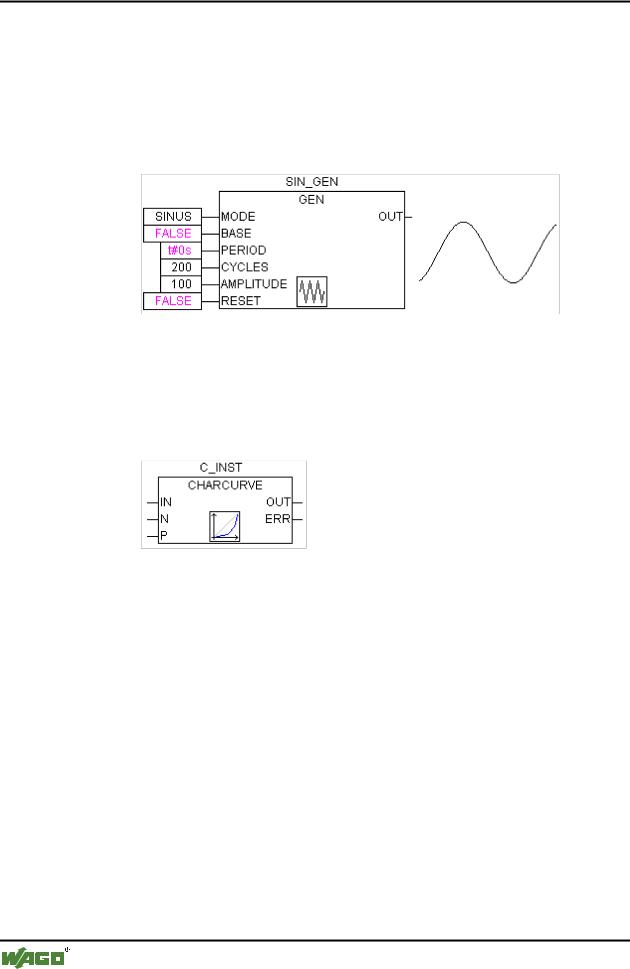
CHARACTERISTIC_LINE:CHARCURVE;

KL:ARRAY[0..10] OF POINT:= (X:=0,Y:=0), (X:=250,Y:=50), (X:=500,Y:=150), (X:=750,Y:=400), 7((X:=1000,Y:=1000));

COUNTER:INT;

...

END_VAR

Then we supply CHARCURVE with for example a constantly increasing value:

COUNTER:=COUNTER+10;

CHARACTERISTIC_LINE(IN:=COUNTER,N:=5,P:=KL);

The subsequent tracing illustrates the effect:
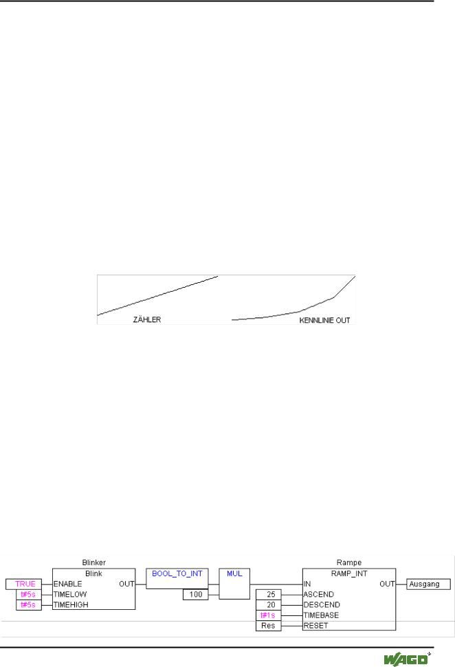
14.7.2RAMP_INT

RAMP_INT serves to limit the ascendance or descendance of the function being fed:

The input consists on the one hand out of three INT values: IN, the function input, and ASCEND and DESCEND, the maximum increase or decrease for a given time interval, which is defined by TIMEBASE of the type TIME. Setting RESET to TRUE causes RAMP_INT to be initialised anew.

The output OUT of the type INT contains the ascend and descend limited function value.

When TIMEBASE is set to t#0s, ASCEND and DESCEND are not related to the time interval, but remain the same.

Example in CFC:

WAGO-I/O-SYSTEM 759 WAGO-I/O-PRO 32