Материал: Analogdrive
SoftMotion: DriveInterface: Analog
SoftMotion: DriveInterface: Analog
Last update: 16.04.2007
Hardware interface |
I/Os from standard PLC configuration |
|
|
Supported drives |
any +/-10V frequency converters |
|
|
Runtimes |
any |
|
|
Author |
Hilmar Panzer |
|
|
Components |
Analogdrive.lib |
|
|
Version |
1.9.3.0 |
|
|
CONTENT |
|
|
|
1 PARAMETERS IN PLC CONFIG |
2 |
||
1.1 |
BusInterface ........................................................................................................................ |
2 |
|
1.2 |
AxisGroup ........................................................................................................................... |
2 |
|
1.3 |
supported Drive.wControlType.......................................................................................... |
2 |
|
1.4 |
Additional structure Analog_AXIS_REF ............................................................................ |
2 |
|
1.5 |
Configuration data.............................................................................................................. |
3 |
|
1.5.1 |
Cyclic Inputs .................................................................................................................. |
3 |
|
1.5.2 |
Cyclic Outputs................................................................................................................ |
3 |
|
2 FEATURES |
4 |
2.1 Additional function blocks |
.................................................................................................4 |
© 3S - Smart Software Solutions GmbH
Analogdrive.doc |
Page 1 of 4 |

SoftMotion: DriveInterface: Analog
1 Parameters in PLC config
1.1BusInterface
wParam1 |
Not used |
|
|
wParam2 |
Not used |
|
|
dwParam1 |
Not used |
|
|
dwParam2 |
Not used |
|
|
1.2AxisGroup
wParam1 |
Not used |
|
|
wParam2 |
Not used |
|
|
wParam3 |
Not used |
|
|
wParam4 |
Not used |
|
|
dwParam1 |
Not used |
|
|
dwParam2 |
Not used |
|
|
dwParam3 |
Not used |
|
|
dwParam4 |
Not used |
|
|
1.3supported Drive.wControlType
T / - no |
V/V yes |
V/P yes |
P/P yes |
PV/PV yes |
V/- no |
CONF yes |
|
|
|
|
|
|
|
The cyclically sent data must consist of: fSetPosition and/or fActPosition.
The received data must consist of: fActPosition and/or fActVelocity.
1.4Additional structure Analog_AXIS_REF
name |
Type |
|
|
|
|
in |
Analog_AXIS_REF |
internal use: input structure of cyclic data |
out |
AnalogOutput |
internal use: input structure of cyclic data |
controller |
AnalogPositionController |
internal use |
hes |
SMC_HardwareEndSwitches |
internal use |
dwIncperTurn |
DWORD |
number of increments per turn |
dwEncoderCounterModulo |
DWORD |
Modulo value of Encoder input |
dwMaxPositionDiff |
DWORD |
maxmimum position lag (0: don’t watch) |
dwOldActPosition |
DWORD |
internal use |
dwActPosition |
DWORD |
internal use |
dwPosOffset |
DWORD |
internal use |
bOldCaptureOccured |
BOOL |
internal use |
bInvertDirection |
BOOL |
FALSE: dwActPosition and fSetVelocity |
|
|
|
© 3S - Smart Software Solutions GmbH
Analogdrive.doc |
Page 2 of 4 |

SoftMotion: DriveInterface: Analog
run in same direction
1.5Configuration data
During the first IEC cycle the following parameters must be configured:
Drive_MS.dwIncPerTurn |
DWORD |
Increments per turn (encoder resolution) |
|
|
|
|
|
Drive_MS.dwMaxPositionDiff |
DWORD |
Maximum position lag in increments (0: switched |
|
|
|
off) |
|
|
|
|
|
Drive_MS.dwEncoderCounterModul |
DWORD |
Modulo value of encoder input (dwActPosition) |
|
o |
|
|
|
|
|
|
|
Drive_MS.bInvertDirection |
BOOL |
FALSE: dwActPosition and fSetVelocity run in |
|
|
|
same direction |
|
|
|
|
|
Drive_MS.out.fMaxVelocityPos |
LREAL |
The maximum velocity value (technical units) in |
|
|
|
positive direction, with the corresponding output |
|
Drive_MS.out.iMaxVelocityPos |
INT |
||
value iMaxVelocityPos |
|||
|
|
||
|
|
|
|
Drive_MS.out.iZeroVelocity |
INT |
output value which produces standstill at drive |
|
|
|
|
|
Drive_MS.out.fMinVelocityNeg |
LREAL |
The maximum velocity value (<0; technical units) |
|
|
|
in negative direction, with the corresponding |
|
Drive_MS.out.iMinVelocityNeg |
INT |
||
output value iMinVelocityPos |
|||
|
|
||
|
|
|
|
Drive_MS.controller.fDeadTime |
LREAL |
Deadtime due to communication and system |
|
|
|
delay in cycles |
|
|
|
|
|
Drive_MS.controller.fKP |
LREAL |
P-factor of the position controller |
|
|
|
|
1.5.1Cyclic Inputs
The following values must be received and updated cyclically in the application:
Name |
Type |
|
|
|
|
Drive_MS.in.bEndLimitPos |
BOOL |
limit switch in positive direction (if not used: TRUE) |
Drive_MS.in.bEndLimitNeg |
BOOL |
limit switch in negative direction (if not used: TRUE) |
Drive_MS.in.dwActPosition |
DWORD |
Encoder Position |
Drive_MS.in.bLatchOccured |
BOOL |
Optional: rising edge indicates that a latch has taken |
|
|
place |
Drive_MS.in.dwLatchPosition |
DWORD |
Optional: Latched position |
|
|
|
1.5.2Cyclic Outputs
The following values must be transmitted cyclically from the application to the drive system:
name |
Type |
|
|
|
|
bEnable |
BOOL |
put power on axis |
iSetVelocity |
INT |
set velocity value |
bEnableLatch |
BOOL |
TRUE: enable latch mechanism |
|
|
|
© 3S - Smart Software Solutions GmbH
Analogdrive.doc |
Page 3 of 4 |
SoftMotion: DriveInterface: Analog
2 Features
o RegulatorOn
o Detecting and acknowledging lag errors
o any gearing factors (dwRatioTechUnitsDenom/iRatioTechUnitsNum)
o linear/rotary axes
o controlling modes: position (0/3), velocity (2): set param 1091 byControllerMode
o limit switches generate an error, when not TRUE.
o homing via SMC_Homing
o latching (use MC_TouchProbe with iTriggerNumber:=1)
2.1Additional function blocks
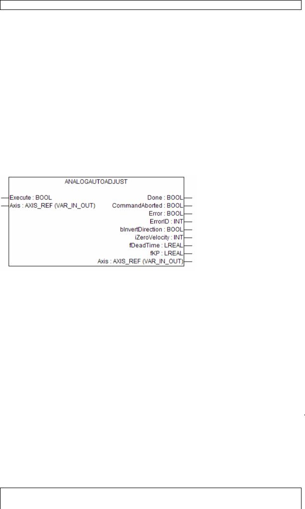
AnalogAutoAdjust
This function block runs the motor and automatically adjusts the controller parameters bInvertDirection, iZeroVelocity, fDeadTime, fKp. It must be handled with care as the drive may act instable during this procedure and move quickly.
It may only be used, when at least the following parameters are already set:
Drive_MS.dwIncPerTurn |
DWORD |
Increments per turn (encoder resolution) |
|
|
|
|
|
Drive_MS.dwMaxPositionDiff |
DWORD |
Maximum position lag in increments (0: switched |
|
|
|
off) |
|
|
|
|
|
Drive_MS.dwEncoderCounterModul |
DWORD |
Modulo value of encoder input (dwActPosition) |
|
o |
|
|
|
|
|
|
|
Drive_MS.out.fMaxVelocityPos |
LREAL |
The maximum velocity value (technical units) in |
|
|
|
positive direction, with the corresponding output |
|
Drive_MS.out.iMaxVelocityPos |
INT |
||
value iMaxVelocityPos |
|||
|
|
||
|
|
|
|
Drive_MS.out.iZeroVelocity |
INT |
output value which produces standstill at drive |
|
|
|
|
|
Drive_MS.out.fMinVelocityNeg |
LREAL |
The maximum velocity value (<0; technical units) |
|
|
|
in negative direction, with the corresponding |
|
Drive_MS.out.iMinVelocityNeg |
INT |
||
output value iMinVelocityPos |
|||
|
|
||
|
|
|
Before starting this FB, power must be set on the drive. Therefore it is useful to first set Drive_MS.controller.fKP to 0 (no position control loop), then use MC_Power to enable the drive, and finally start this FB.
This FB shouldn’t be called during every startup, but just during commissioning. It’s output shall be read out and set during the first IEC cycle afterwards.
© 3S - Smart Software Solutions GmbH
Analogdrive.doc |
Page 4 of 4 |